
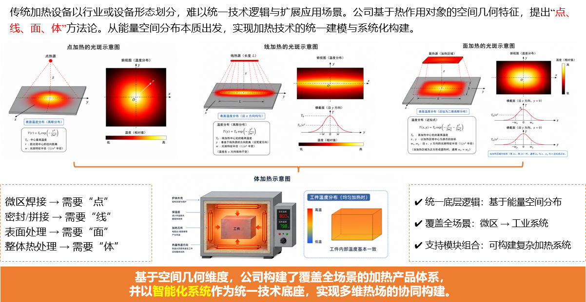
In high-temperature testing, the critical design challenge isn't just "how high can we go," but rather: how heat is spatially applied to the specimen, its rate of change, measurement and control methods, and its ability to synergize with mechanical force, vibration, pressure, vacuum, or atmosphere conditions. Addressing these distinctions, KUCH categorizes thermal loading requirements into four engineering forms—point, line, surface, and volume—to deliver a multidimensional technical system covering localized precise heating, continuous trajectory loading, uniform regional heat flux, and comprehensive thermal environment simulation.
Traditional heating equipment is categorized by industry or form factor, making it difficult to unify technical logic and expand application scenarios. Our company proposes a "Point, Line, Surface, Volume" methodology based on the spatial geometric characteristics of the heated object. Starting from the fundamental energy distribution in space, we achieve unified modeling and systematic construction of heating technology. Powered by an intelligent system as the foundational platform, we enable the coordinated construction of multi-dimensional thermal fields.
1. Why Do We Need Multi-Dimensional Hot Loading (Point, Line, Plane, and Body)?
Traditional heating equipment is typically categorized by heat source type, such as laser, quartz lamp, electromagnetic induction, and resistance furnace heating. However, for research testing and engineering validation, customers are less concerned with "which heat source to choose" and more focused on "what temperature range, time profile, and boundary conditions must be applied." The same heat source can generate distinct spatial thermal fields through focusing, shaping, scanning, arraying, or zone control. Conversely, different heat sources may achieve similar loading profiles.
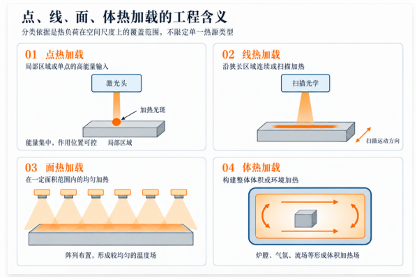
Therefore, "point, line, plane, and volume" do not replace classification based on heat source mechanisms. Instead, they constitute an engineering language tailored to test requirements: points emphasize localization; lines highlight continuous paths or elongated regions; planes focus on two-dimensional coverage and uniformity; volumes address the specimen as a whole and its surrounding thermal boundaries. This framework guides system design by starting with the test object and then determining the heat source, optical path or coil configuration, thermal field control, temperature measurement methods, and safety provisions in reverse.
2. Targeted Heat: Deliver heat exactly where it's needed
Point thermal loading targets small areas, local hot spots, or specified locations for rapid heat input. In this context, "point" refers to a localized region relative to the specimen scale, not a geometrically infinitesimal point. Laser technology, characterized by non-contact operation, concentrated energy, and precise position control, is a key approach for implementing point thermal loading. For conductive materials, locally arranged induction coils can also create highly concentrated heating zones. Relevant studies indicate that laser-based thermal fatigue methods are well-suited for rapid cyclic heating of small regions.
The challenge of engineering hot-loading isn't just about increasing power—it's controlling effective heat absorption. Surface state, laser wavelength, incident angle, spot size, and energy distribution all affect temperature rise. High-reflectivity metals, coatings, or roughness changes can cause absorption rates to vary with temperature. Therefore, system design must account for beam shaping, working distance, surface absorption characteristics, infrared thermometry band avoidance, and necessary heat flux calibration.
- Application Scenarios: Local thermal shock, hot spot simulation, heating of small-scale specimens, gauge section heating in thermo-mechanical fatigue, and non-contact heating outside vacuum observation windows.
- Key Metrics: Spot Size and Shape, Energy Distribution, Peak Power Density, Working Distance, Heating Rate, Position Repeatability, and Temperature Measurement Interference Resistance.
- Design consideration: Do not rely solely on the laser's rated power to assess thermal capability. Instead, perform heat balance and transient analysis by accounting for specimen geometry, material thermal properties, cooling boundary conditions, and absorptivity.
3. Wire Hot-Loading: Bridging Discrete Heat Sources and Continuous Thermal Fields
Line heat loading better approximates actual boundary conditions when the test object involves welds, cutting edges, narrow bands, circular paths, or scenarios requiring simulated moving heat sources. It can be generated either by a linear laser spot in a single pass or by scanning a point laser at high speed to create an equivalent thermal trajectory. Alternatively, it can be achieved using elongated lamp arrays, bar-shaped resistive elements, or sensors arranged along the structure. In other words, "line" refers to the form of heat application, not a fixed equipment type.
Line thermal loading requires careful handling of power distribution along the path, scan speed, trajectory continuity, and end effects. For scanning methods, local dwell time determines energy input per unit length; for static line heat sources, differences between the center and edges must be addressed. For ring-shaped, curved, or complex geometries, unify the heat source orientation, motion mechanism, and sample coordinate system to prevent geometric deviations from causing temperature errors.
- Application scenarios: thermal simulation of welds and narrow strips, localized circumferential or axial heating, moving heat source replication, and zoned heating of elongated specimens.
- Key Metrics: Line Width, Effective Length, Uniformity Along Path, Scan Speed, Trajectory Repeatability, Corner and End Thermal Accumulation.
4. Surface Heat Flux Reload: From "Visible" to "Usable Heat Flux Field"
Facial heat loading creates controlled radiative or induced thermal fields within a 2D area, addressing common needs in thermal protection materials, structural thermal qualification, rapid thermal shock testing, and large-area dynamic heating. Common approaches include laser homogenization and beam expansion, scanning stitching, quartz lamp arrays, radiation panels, and planar resistive heating. Quartz lamp arrays achieve high-response radiative boundaries through reflectors, array arrangement, and zone-based power control. Published data also indicates that quartz lamp radiant heating systems can employ multi-zone closed-loop control to track set temperature profiles across different zones.
The core of surface heating is not simply "enlarging the spot," but ensuring that heat flux or temperature distribution within the effective area meets test objectives. Array pitch, reflector geometry, radiation distance, incident angle, edge heat loss, and material spectral absorption all influence the final thermal field. Studies commonly evaluate quartz lamp array radiative heat flux on heated surfaces using combined modeling and measurements. When heating larger areas or curved specimens, zoning, edge compensation, and multi-point thermocouples are typically required; thermal imaging may also be used to verify spatial uniformity when necessary.
- Application scenarios: thermal protection material qualification, panel and shell thermal load simulation, rapid thermal shock, localized heat flux loading, and temperature gradient testing.
- Key Metrics: Effective Heating Area, Heat Flux Density, Uniformity, Zone Count, Dynamic Response, Edge Effects, and Cooling Capacity.
- Design Focus: "Temperature Uniformity" and "Heat Flux Uniformity" are distinct concepts; the former is also influenced by specimen thermal conductivity, thickness, back-side heat dissipation, and boundary constraints.
5. Body Heat Loading: Establishing the thermal environment for the entire test specimen
When the objective shifts from localized heat input to whole-specimen heating, soaking, thermal cycling, or atmosphere simulation, design priorities move to the "bulk thermal loading" level. Such systems typically comprise a furnace or environmental chamber, heating elements, insulation structures, circulation or purge gas paths, multi-zone temperature sensing, and safety systems. They can be combined with vacuum, inert atmospheres, pressure, mechanical loading, or vibration conditions. Public documentation on thermal-vacuum facilities indicates that whole-environment thermal testing is commonly used for environmental cycling, performance evaluation, and design validation of components, subsystems, and materials.
Thermal load testing prioritizes spatial temperature distribution, furnace thermal inertia, specimen fixturing, airflow organization, heating/cooling profiles, and environmental compatibility. For large specimens, simply increasing total power does not guarantee a uniform temperature field; heating zone segmentation, recirculation ducts, furnace lining heat capacity, vented heat dissipation, and thermocouple placement all impact control performance. If the test includes vibration or mechanical loads, furnace structure, loading channels, thermal expansion compensation, and sensor wiring must also be designed in tandem.
- Application scenarios: high-temperature exposure, thermal cycling, atmosphere or vacuum environment simulation, large-scale structural temperature field modeling, and coupled thermo-mechanical or thermo-vibration testing.
- Key Metrics: Usable Volume, Temperature Range, Uniformity, Ramp Rate, Atmosphere & Pressure Conditions, Thermal Inertia, Interface Compatibility.
6. How to match different loading states?
Points, lines, surfaces, and volumes do not represent a hierarchy from low to high, nor are they four mutually exclusive equipment categories. A complex test may involve multiple scales simultaneously: for instance, establishing a baseline temperature across the entire chamber using a furnace, then adding localized hot spots with lasers; providing surface heat flux via a quartz lamp array while separately compensating edge regions; or achieving rapid local heating through induction and completing the cycle with cooling airflow. The optimal solution should be based on the test boundary conditions rather than relying on a single heat source to cover all scenarios.
| Loading | Primary Goal | Common Technical Approaches | Conditions to be confirmed first |
|---|---|---|---|
| Click | Precise locally, fast response | Focused laser, localized sensing | Effective size, material absorption/conductivity, peak heat flux, temperature measurement interference |
| Line | Continuous trajectories or narrow areas | Linear spot, scanning heat source, linear lamp array/resistor | Line width, length, speed, end effects, trajectory accuracy |
| Face | Uniform or segmented loading in 2D regions | Homogenized laser, quartz lamp array, radiation panel | Area, Uniformity, Heat Flux Density, Distance, Zoning & Edge Compensation |
| Body | Overall Heating and Environmental Simulation | Resistance furnace, environmental chamber, circulating airflow, multi-zone radiation | Working volume, atmosphere/vacuum, uniformity, thermal inertia, interface conditions |
VII. KUCH builds a "complete hot-reload chain," not just a simple combination of heat sources.
The value of an advanced thermal load system depends on whether a complete link is established between the heat source and the test boundary. A heater alone does not equate to a usable test system. KUCH integrates laser, quartz lamp, electromagnetic induction, and resistive heating technologies into a unified solution that covers optical or electromagnetic design, mechanical structure, temperature and heat flux measurement, control strategies, cooling, safety interlocks, and host computer interfaces.
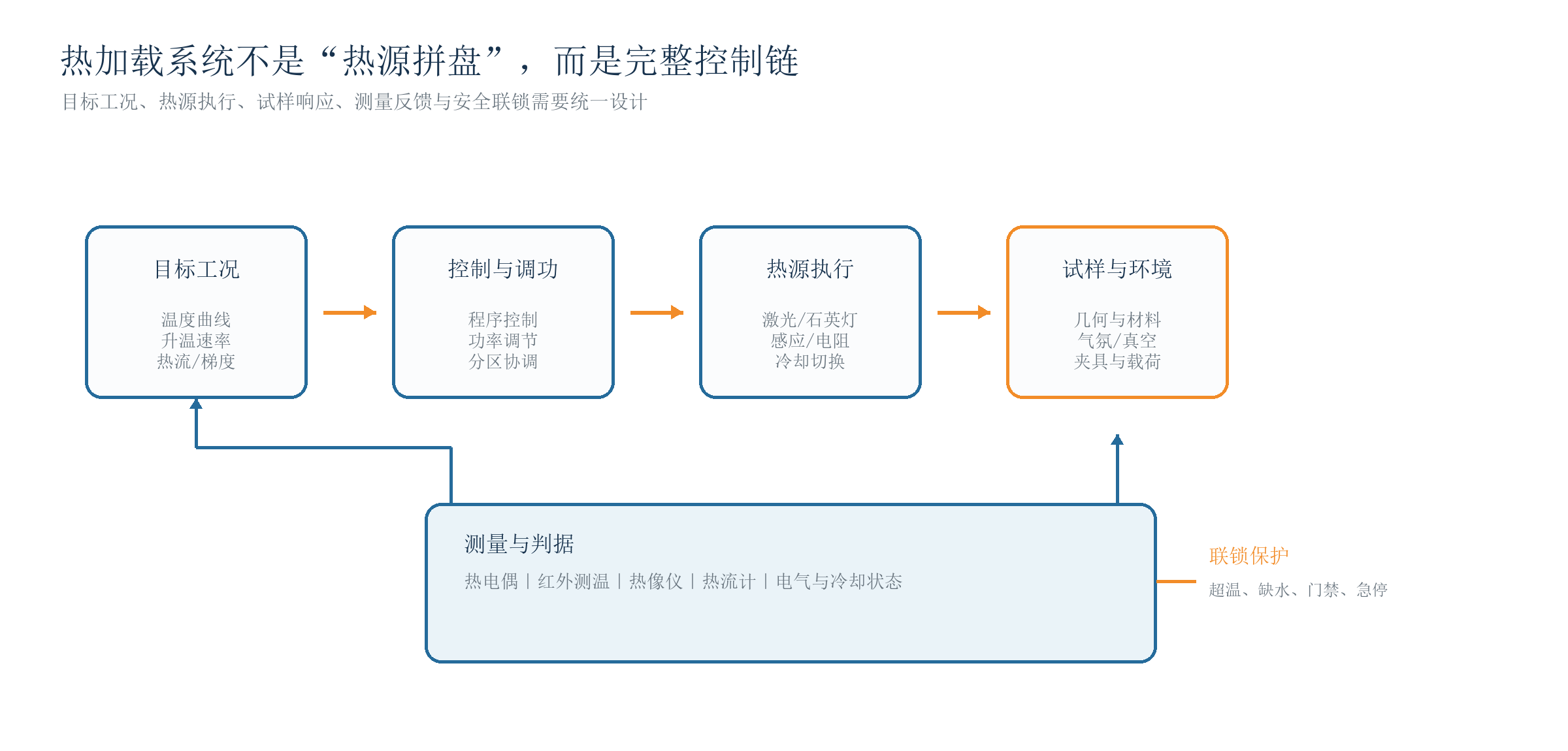
At the control level, three common approaches should be distinguished based on test objectives: temperature closed-loop control uses thermocouple or infrared measurements as feedback; power curve control operates according to a preset power profile or a calibrated operating curve; and heat flux feedback control requires appropriate heat flux sensors and their calibration chains. These methods differ in their measurement targets and control goals and should not be used interchangeably. For dynamic processes, sensor response time, sampling frequency, control cycle, and thermal inertia must also be considered; otherwise, static accuracy does not reflect transient tracking capability.
Infrared thermometry is influenced by material emissivity, viewing angle, window transmittance, background radiation, and heating source wavelength. Thermocouples are affected by installation method, thermal contact, response lag, and lead interference. Literature reviews also indicate that high-temperature loading methods such as laser, induction, and resistance heating each have specific application ranges; reliable data depend on systematic control of temperature gradients and measurement errors. In induction heating, frequency, electrical conductivity, and magnetic permeability jointly determine electromagnetic field penetration and heat distribution; frequency selection must account for workpiece dimensions and target heating depth.
8. From Requirements to Solution: KUCH Confirms Six Key Boundaries
- Specimen boundary: material, dimensions, surface condition, clamping method, and allowable heated area.
- Thermal Boundary Conditions: Target Temperature, Heating/Cooling Rate, Heat Flux Density, Uniformity, Gradient, and Cycle Profile.
- Environmental boundaries: air, inert atmosphere, vacuum, pressure, and requirements for fume or vapor handling.
- Measurement range: Thermocouples, infrared thermometers, thermal imaging cameras, or heat flux sensors—range, spectral band, response time, and installation conditions.
- Coupling boundary: Synchronize with tension, compression, fatigue, vibration, rotation, or flow conditions.
- Engineering Boundaries: Power, Cooling, Site, Mobility, Interfaces, Interlocks, and Future Scalability.
These boundary conditions transform the vague requirement for "a heating system" into a calculable, design-ready, and testable thermal loading task. For research projects with unclear specifications, KUCH can start by defining target operating conditions and then systematically complete heat source selection, thermal field design, control and measurement strategies, and structural integration.
Conclusion: From Heat Source Capability to Operating Condition Construction
Point, line, plane, and volume do not represent four isolated products; they represent four scales for understanding thermal loading. Localized heating focuses on energy concentration and positional control. Continuous regions emphasize trajectory and consistency along the path. Plane thermal fields prioritize uniformity and zonal regulation. The overall environment considers spatial temperature distribution and compatibility with multiple conditions. Only by integrating heat sources, specimens, environmental conditions, measurements, and controls into a single system can "heating" truly support material evaluation, structural assessment, and dynamic testing.
KUCH will continuously enhance its multi-dimensional hot-loading technology framework across diverse research and engineering scenarios, providing universities, research institutes, and high-end equipment development organizations with end-to-end technical support—from requirements analysis and solution design to system integration and test validation.