
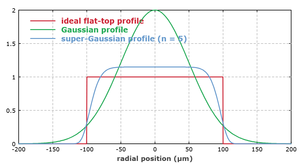
1. Why is the laser spot often "bright in the center and dim at the edges"?
For an ideal TEM00 laser beam, the irradiance on a given cross-section typically follows a Gaussian distribution: highest at the center and gradually decreasing outward. The common expression is I(r) = I0·exp(-2r²/w²), where w usually corresponds to the 1/e² intensity radius. While actual high-power fiber lasers and multimode beams may not strictly conform to the ideal Gaussian model, it remains very common for energy to be more concentrated at the center and weaker at the edges.
For laser heating, this spatial distribution directly maps to heat input: the center receives higher irradiance, causing the sample to heat up faster in the middle than at the edges. Therefore, when experiments require temperature uniformity, heat flux consistency, or repeatability over a large area, simply expanding the beam spot to the target size is insufficient; beam shaping must also be considered.
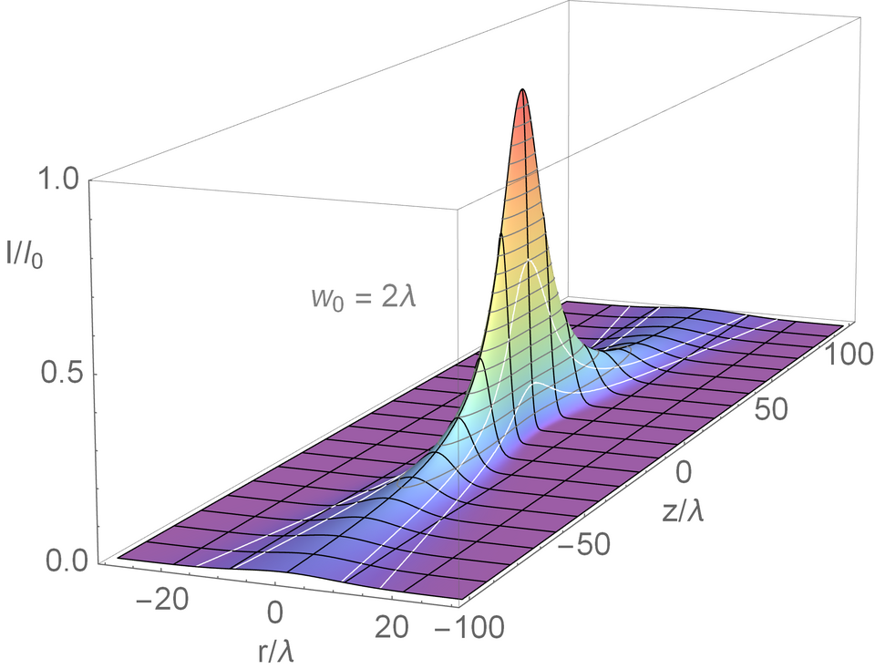
II. How is a flat-top beam profile formed?
A top-hat (flat-top) beam aims to maintain near-constant irradiance within a specified working area while keeping the edge transition within acceptable limits. Common engineering approaches include refractive field mapping, diffractive optical elements (DOE), and micro-lens array (MLA) homogenizers. While their mechanisms differ, all fundamentally redistribute the spatial energy of the input beam.
2.1 Refractive Field Mapping
Refractive beam shaping typically employs a set of aspheric optical elements to redirect light rays at different radial positions, remapping the over-concentrated energy from the Gaussian center to the outer regions. Hoffnagle and Jefferson reported a Gaussian-to-flat-top beam conversion system using two aspheric lenses in Applied Optics, with quantitative validation of actual output. While these methods offer high efficiency, they are generally sensitive to input beam diameter, position, and collimation state.
2.2 DOE and Microlens Array
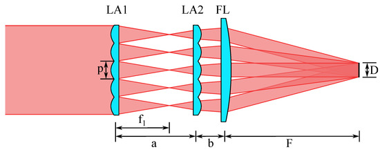
DOE uses phase distribution design to leverage diffraction and form a specified intensity profile on the target plane, making it suitable for circular, square, or even more complex target spots. A microlens array splits the incident light into multiple sub-beams, which are then superimposed at the target plane via a Fourier lens to average out spatial non-uniformities in the original beam. For systems requiring large-area uniform illumination or square spots, microlens arrays are a common engineering solution.
III. What Does Real-World Testing Show About the Effects of Uniformity?
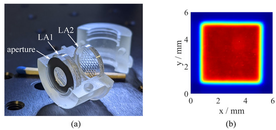
Schwarz et al. [0] constructed a beam homogenization system in their open-access paper, consisting of two sets of 8×8 microlens arrays and a Fourier lens. The first array splits the input beam into multiple sub-beams, while the second array, together with the Fourier lens, causes these sub-beams to overlap in the target region. Due to the square apertures of individual microlenses, a square Top-Hat intensity profile was achieved.
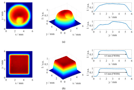
The comparative results in the paper are highly intuitive: before homogenization, the intensity distribution shows significant fluctuations; after passing through the microlens array, the 2D distribution transforms into a square beam spot with sharp boundaries and a relatively flat plateau region. Under these experimental conditions, the Full Width at Half Maximum (FWHM) of the Top-Hat profile is approximately 4.5 mm. Based on the ISO 13694:2000(E) standard and a 90% threshold adopted at the time, the authors report a beam uniformity of 1.8%, a plateau uniformity of 2.1%, and a flatness factor of 95.2%. These values should be interpreted as results specific to this particular system and evaluation method, rather than universal metrics achievable by all beam homogenization systems.
| Evaluation Metrics | Paper Measured Values | Evaluation Criteria |
|---|---|---|
| Top-Hat Full Width at Half Maximum | Approximately 4.5 mm | 8×8 microlens array + Fourier lens homogenization system |
| Beam uniformity | 1.8% | ISO 13694:2000(E), 90% threshold |
| Plateau uniformity | 2.1% | ISO 13694:2000(E), 90% threshold |
| Flatness factor | 95.2% | ISO 13694:2000(E), 90% threshold |
IV. Why Does Having a Diffuser Lens Not Guarantee Uniformity?
Beam shaping isn't complete once a lens is mounted. The actual output depends on multiple factors: input beam diameter and divergence, M², wavelength, lens spacing, working distance, element decentering and tilt, coherence, and thermal effects at high power. Devices like DOEs and refractive field mapping optics often require specific input conditions. Deviations from these design parameters alter the flatness, size, and edge profile of the target beam.
Therefore, a complete uniform laser spot system typically includes the entire chain: "light source → collimation/beam expansion → shaping/homogenization → imaging or focusing → work surface inspection." When designing, do not focus solely on the final spot size; you must also account for the effective work surface position, allowable variation in working distance, power density, component damage thresholds, and subsequent temperature measurement methods.
V. How to professionally express "uniformity"?
Uniformity: 98%. Without specifying the evaluation region, threshold, measurement plane, and calculation method, the technical meaning is incomplete. ISO 13694:2026, published in 2026 (7), is currently the 4th edition of ISO 13694. It defines methods for measuring laser irradiance (or energy fluence) spatial distribution and its spatial characteristic parameters. Therefore, in engineering communication, it is more appropriate to report the test plane, effective area, sampling equipment, threshold/evaluation method, and corresponding results together, rather than providing an isolated percentage value.
6. For laser heating, what truly matters isn't just whether the spot is uniform.
A flat-top beam profile addresses irradiance distribution at the optical level. However, achieving a uniform temperature field in the final part also depends on material properties such as laser wavelength absorption, surface condition, thickness, thermal conductivity, boundary cooling conditions, and heating duration. In other words, "optical uniformity" does not automatically guarantee "thermal uniformity." For high-temperature thermal loading systems, beam shaping, power control, infrared/thermocouple monitoring, and thermal field validation must be designed as an integrated solution.
Transforming a Gaussian beam into a flat-top beam fundamentally converts "laser energy presence" into "controllable, quantifiable spatial thermal input." For experiments involving material heat treatment, thermal cycling, high-temperature loading, and localized heat flux simulation, this capability is often more critical than simply increasing laser power.
References
- [1] Hoffnagle J A, Jefferson C M. Design and performance of a refractive optical system that converts a Gaussian to a flattop beam. Applied Optics, 2000, 39(30): 5488-5499.
- [2] Schwarz S, Götzendorfer B, Rung S, et al. Compact Beam Homogenizer Module with Laser-Fabricated Lens Arrays. Applied Sciences, 2021, 11(3): 1018.
- [3] ISO 13694:2026. Optics and photonics — Lasers and laser-related equipment — Test methods for laser beam irradiance (fluence) distribution. Edition 4, 2026-07.
- [4] Xue L, et al. Fabrication of Random Microlens Array for High-Efficiency Laser Beam Homogenization. Micromachines, 2020, 11(3): 338.