
Product Center
Heating equipment series tailored for research scenarios
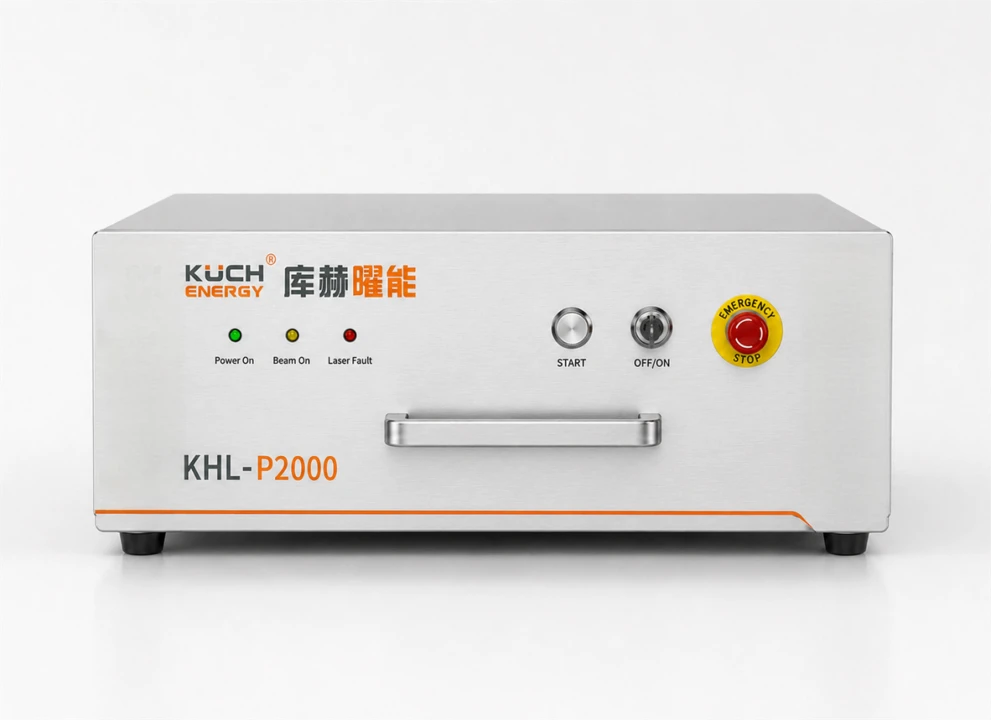
KHL-P2000 Laser Spot Heating System
Product Overview
The KHL-P2000 Laser Spot Heating System is a 2000-W high-power-density laser local thermal loading solution designed for high-temperature material research, extreme thermal environment simulation, material performance testing, and advanced manufacturing process development. Using a high-power semiconductor laser as the heat source, the system delivers precise energy to target areas via fiber-optic transmission, beam shaping, and focusing modules to achieve rapid heating, localized thermal treatment, and non-contact loading. Typically comprising a laser source, optical transmission/focusing module, temperature sensing module, and control system, it enables closed-loop temperature control through infrared thermometry or thermal imaging to meet precision thermal process requirements in both research and engineering applications.
Product Positioning
2000 W high-power-density thermal loading
High-power semiconductor lasers transmit energy via optical fibers, shape and focus the beam to precisely target specific areas, enabling rapid heating, localized thermal treatment, and non-contact thermal loading.
Precision Thermal Process Control Platform
Composed of a laser source, optical transmission/focusing system, and temperature detection & control module. Enables closed-loop temperature control via infrared thermometry or thermal imaging to meet precise thermal process control requirements in research and engineering applications.
Product Type
How it works
The system uses a high-power semiconductor laser as the heat source. Laser energy is delivered via fiber optic cable, shaped, and focused to precisely target specific areas for rapid heating, localized treatment, and non-contact thermal loading. The device supports two beam modes—flat-top and Gaussian—with customizable spot sizes ranging from 2 to 25 mm. Integrated with non-contact temperature measurement tools such as infrared thermometers and thermal cameras, it enables closed-loop temperature control with real-time laser power adjustment. Both continuous output and power modulation operating modes are supported.
The system comprises five modules: laser heat source, optical shaping, temperature sensing, control, and mechanical integration interfaces. The laser heat source module delivers stable 2000 W laser output. The optical shaping module manages beam transmission, focusing, and energy distribution control. The control module handles laser power adjustment, program execution, alarms, and safety interlocks. The mechanical integration interface supports installation on experimental platforms and automated systems. Compared to traditional furnace heating methods, this system offers faster thermal response, precise targeting, and a smaller heat-affected zone, meeting experimental requirements for materials under extreme temperature gradients and rapid thermal cycling conditions.
Important Notice:The typical temperature range is 1000~2000℃, depending on material absorptivity and operating conditions. Formal projects shall follow the agreed test conditions and acceptance criteria.
Core Advantages
A local thermal loading system is built using a 2000 W high-power-density laser transmitted via fiber and shaped/focused by beam optics. It features fast thermal response, precise targeting, closed-loop temperature control, and extensibility for complex thermal loading processes.
2000 W High-Power Laser Output
Meets rapid heating requirements for high-temperature materials such as metals, superalloys, ceramics, and composites, enabling localized thermal loading with high heat flux density.
High-precision local heating
Laser energy is concentrated on the target area, resulting in a minimal heat-affected zone. Ideal for localized thermal cycling, thermal shock, and gradient temperature field construction.
Flexible Beam Shaping
Supports configurable spot sizes and energy distribution modes, optimized for material absorption characteristics and experimental requirements.
Rapid Response and Closed-Loop Control
Integrates infrared thermometry and thermal imaging for real-time laser power adjustment, enhancing temperature control stability.
Modular integrated design
Integrates with test rigs, motion platforms, high-temperature testing systems, and automated equipment.
Key Technical Specifications
| Device Model | KHL-P2000 |
| Heating Method | Laser non-contact point heating |
| Laser Output Power | 2000 W |
| Power adjustment range | 10~100% |
| Laser wavelength | 915 nm / 976 nm |
| Spot Size | 2~25 mm (customizable) |
| Beam Mode | Flat-top beam / Gaussian beam |
| Typical temperature range | 1000~2000°C (varies based on material absorption rate and operating conditions) |
| Fiber Length | Approx. 10 m (customizable) |
| Output Interface | QBH Interface |
| Work Mode | Continuous Output / Power Modulation |
| Cooling Method | liquid cooling |
| Power Requirements | AC 220 V / AC 380 V (as configured) |
| Work Environment | 10~40℃ |
Typical Applications
High-temperature alloy thermal cycling and thermal fatigue testing
Thermal Shock Testing of Ceramic Matrix Composites (CMC)
High-Temperature Performance Evaluation of Thermal Barrier Coatings (TBCs)
Localized Annealing and Heat Treatment of Materials
Additive Manufacturing Heat Treatment and Defect Repair
Weld Preheating and Heat-Affected Zone Research
Localized heating of semiconductor materials
High-Temperature Research Test Platform
System Configuration and Control Mode
| Configuration Type | Typical Components | Use Cases |
|---|---|---|
| Basic Power Regulation | Focusing heating head, power controller, cooling assembly, mounting bracket | Process exploration, rapid heating, and experiments with low constant-temperature precision requirements. |
| Closed-loop temperature control | Basic Configuration + Thermocouple or Infrared Temperature Sensor + PID Controller | Target temperature control, heat preservation, over-temperature protection, and repeatability testing |
| Automated Integration Suite | Closed-loop system + 3-axis platform/robotic arm + data acquisition and host computer | Multi-point switching, scan heating, test process linkage, and automatic recording |
Selection Details & Customization Services
Product power, focal length, and control method should be determined jointly based on the sample and test objectives. Before selection, clarify the following information to ensure the spot size, heating rate, and temperature stability meet actual operating conditions:
- Sample material, dimensions, thickness, weight, and surface condition
- Heated zone dimensions, target temperature, allowable ramp-up time, and hold time
- Temperature fluctuation, repeatability, measurement accuracy, and whether temperature curve logging is required
- Fixed-point scanning, multi-position switching, or mobile scanning
- Installation space, working distance, fixture interference, and cooling and safety protection conditions
Available Customizations
- Different power outputs, focal lengths, and target spot sizes
- Fixed, adjustable-angle, or three-axis movable mounting structures
- Thermocouple, Infrared Thermometry, and Dual-Point Verification Solution
- PID closed-loop temperature control, programmable temperature ramping, hold function, and over-temperature protection
- Temperature, Power, and Alarm Data Collection and Export
- Integrate with test machines, robotic arms, fixtures, and automation platforms
Usage and Safety Instructions
- ⚠Strong visible and infrared radiation is emitted during operation. Do not look directly at the light source or focus area. Use appropriate eye and radiation protection equipment.
- ⚠The sample, heating head tip, and surrounding structures may be hot. Install heat guards and allow adequate cooldown time after power-off.
- ⚠Keep the air-cooled channel clear. Do not operate continuously if cooling is abnormal, the reflector surface is contaminated, or electrical connections are loose.
- ⚠Infrared temperature readings are affected by emissivity, angle, and spot size coverage. For highly reflective metals, combine with thermocouples or use a calibrated measurement solution.
- ⚠For adhesives, coatings, and materials that may emit volatiles, evaluate ventilation, smoke extraction, and fire safety conditions.
Product Value
Combining advanced temperature measurement and motion control technologies, we extend heating from single-point to complex thermal loading processes. This delivers a flexible thermal environment solution for high-performance materials research and establishes a comprehensive laser thermal loading system for materials testing and advanced manufacturing.
Energy Distribution Diagram
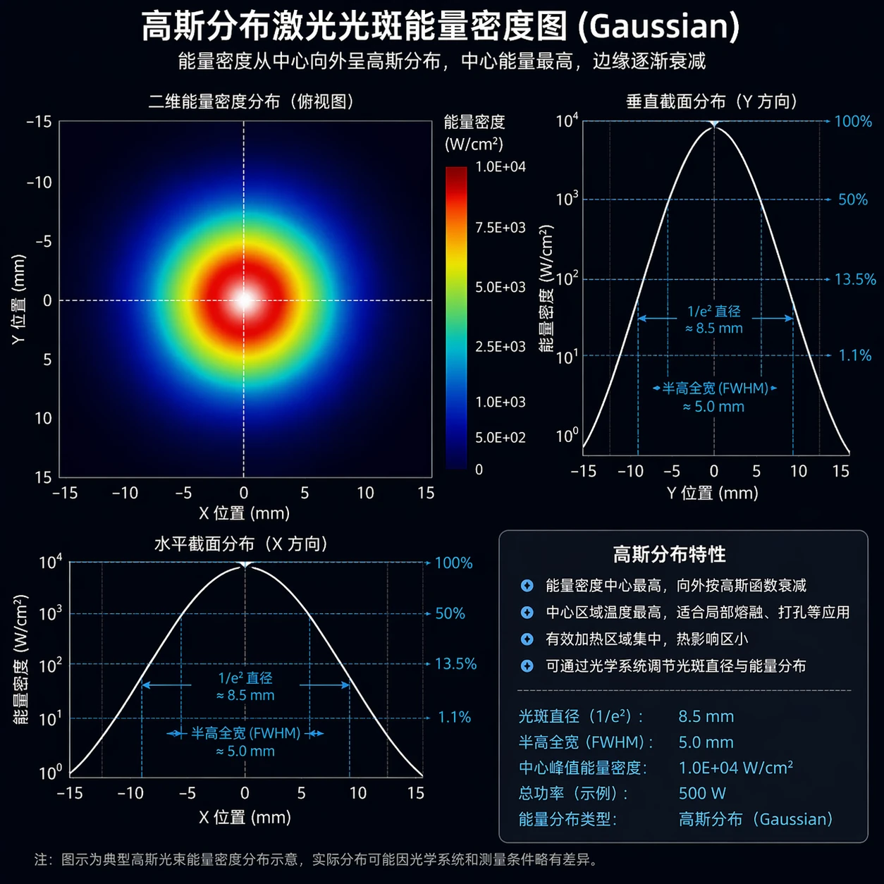
Figure 3Gaussian Beam Energy Density Profile: Energy density follows a Gaussian distribution from the center outward, with peak intensity at the center gradually tapering toward the edges. The central region reaches high temperatures, making it ideal for localized melting and drilling applications with minimal heat-affected zones.
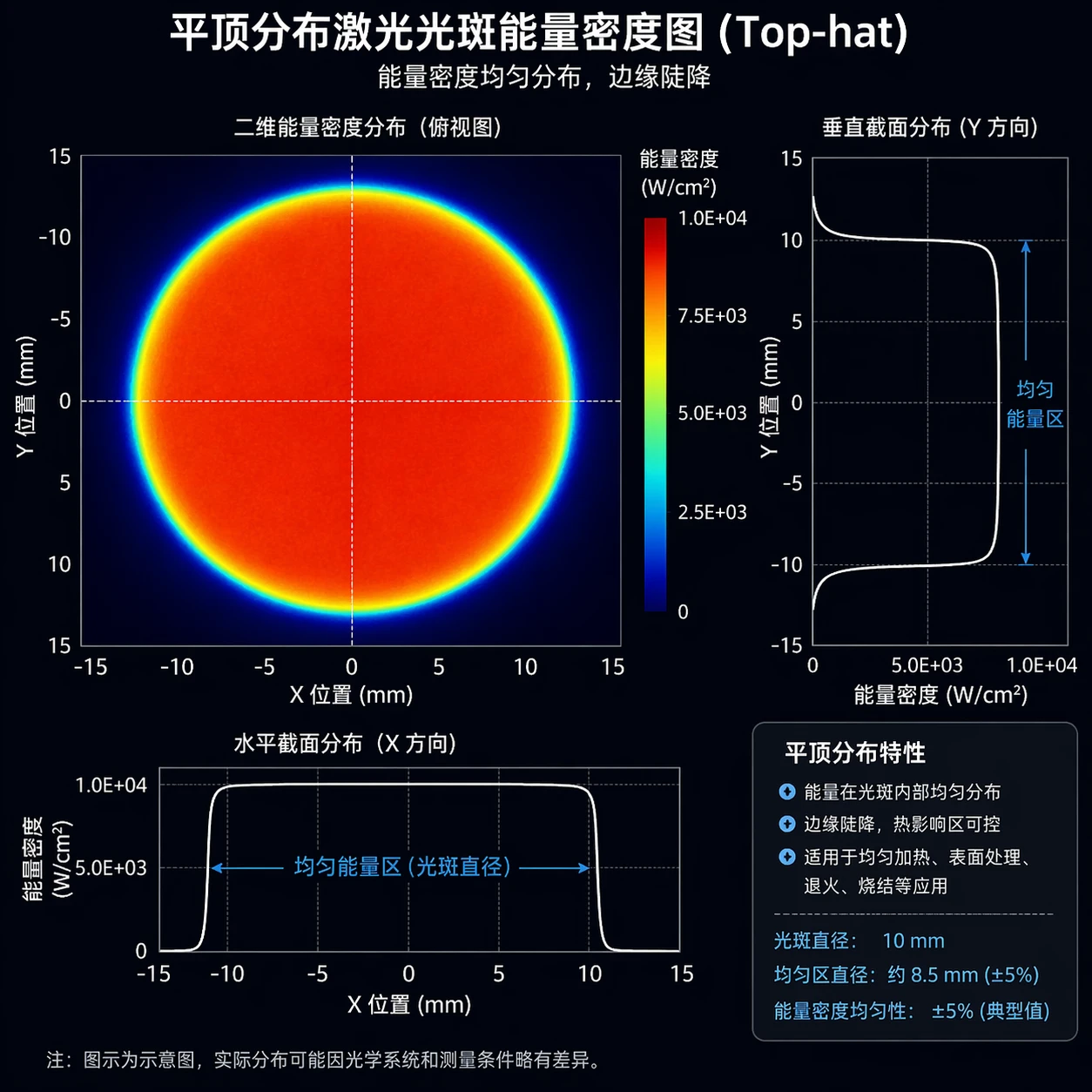
Figure 4Flat-top laser spot energy density map: Energy is uniformly distributed within the spot with a sharp drop-off at the edges. The uniform energy region is controllable, making it ideal for uniform heating, surface treatment, annealing, sintering, and other applications.
Note: The illustration shows a typical beam energy density distribution; actual distributions may vary slightly due to optical system and measurement conditions.