
Non-contact laser heating system for STM vacuum chamber samples
Without introducing contact heat sources into the UHV chamber, use 915–1064 nm near-infrared laser through a fused silica viewport to controllably heat the Φ10 mm sample up to 600 K.
Project Challenges
STM experiments are highly sensitive to vibration, electromagnetic noise, thermal drift, and surface cleanliness. Heating must not compromise the ultra-high vacuum environment (≤10⁻⁹ mbar) while ensuring uniformity of the light spot and temperature control precision.
Use Device
Near-infrared laser (915/976/1064 nm, 15–30 W), top-hat beam shaper, CF40/CF63 fused silica windows, PID temperature control system, motorized shutter
Project Outcomes
Successfully implemented an external, non-contact, localized, and highly responsive heating test system that achieves controllable heating of Φ10 mm samples up to 600 K without introducing any contact heat sources into the UHV chamber.
Case Details
Scanning tunneling microscopy (STM) experiments often require annealing, decontamination, or inducing specific phase transitions of samples in an ultra-high vacuum environment. Traditional internal electric heaters occupy limited space and may introduce material outgassing, electromagnetic coupling, radiation background, and mechanical installation constraints. This project introduces shaped near-infrared laser energy from outside the vacuum chamber to deliver heat precisely to a back-side absorber layer on the sample, forming an external, non-contact, localized, and highly responsive heating test system.
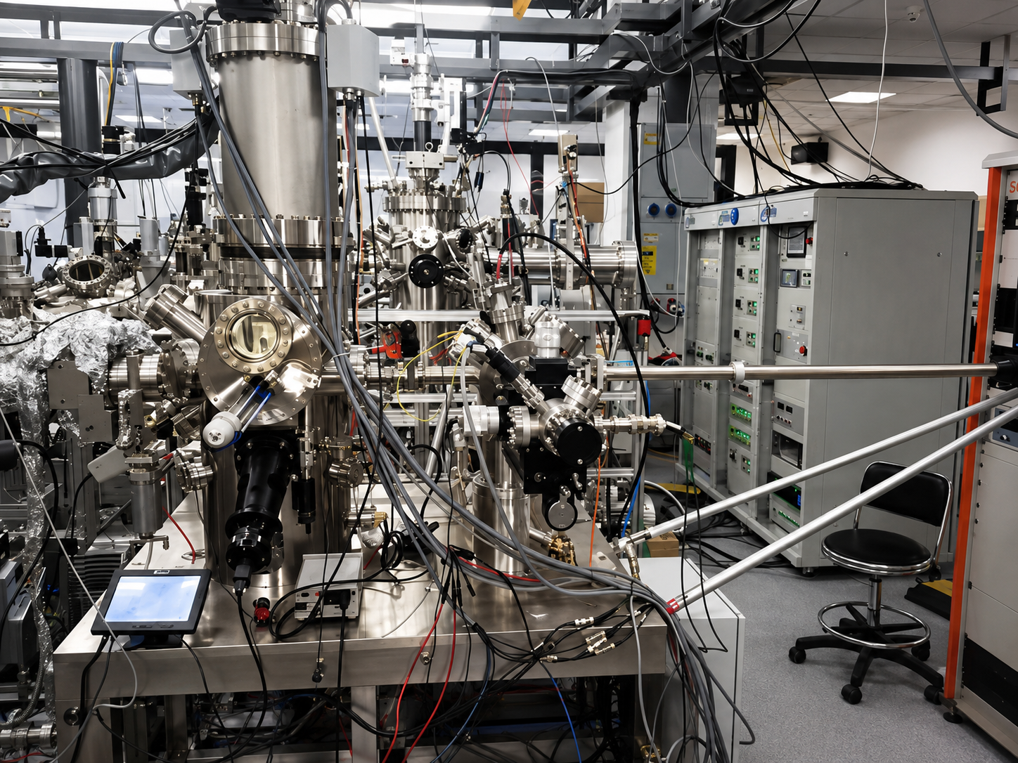
1. Project Challenge: Heating must not disrupt the STM measurement environment.
STM relies on imaging via the extremely weak tunneling current between a probe and the sample surface, making it highly sensitive to vibrations, electromagnetic noise, thermal drift, and surface cleanliness. Therefore, such heating projects must not only ensure they can reach 600 K but also simultaneously control optical, vacuum, thermal, and measurement interference.
- Ultra-high vacuum compatible: Target environment ≤10⁻⁹ mbar. Minimize materials inside the chamber; all windows, supports, and absorptive layers must account for outgassing and vacuum cleanliness.
- Low Vibration and Low Noise: By placing the light source outside the cavity, mechanical actuators and high-current heating elements are kept away from the sample stage, reducing vibration and electromagnetic coupling.
- Spot and temperature field uniformity: With a small sample area of Φ10 mm, the Gaussian beam tends to create a central hotspot. Top-hat beam shaping or high-speed scanning homogenization is therefore prioritized.
- Stray Light and Thermal Drift: Reflected light may enter the detection zone, and localized heating can cause structural thermal drift. Mitigation requires a baffle tube, light trap, and controlled heating strategy.
II. Overall Solution: Non-contact energy transfer via trans-scleral window penetration
| System Modules | Main Configuration | Engineering Function |
|---|---|---|
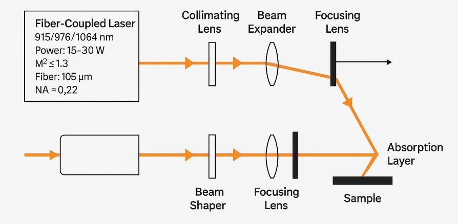
| Near-infrared laser | 915/976/1064 nm, fiber output, 15–30 W, M² ≤ 1.3 | Provides narrowband near-infrared energy with rapid continuous adjustment. |
| Collimating Beam Expander System | Approx. 11 mm collimator, 8–10× beam expander | Reduce beam divergence to establish stable input for subsequent beam shaping and long-distance focusing. |
| Beam shaping module | Top-hat beam shaper or high-speed galvanometer dynamic homogenizer | Improve power density uniformity in the Φ10 mm target area and reduce central hotspots. |
| Focus and Hooding System | 250 mm focusing lens, light trap and baffle | Position the spot on the back of the sample and control reflected and scattered light. |
| Vacuum window interface | CF40/CF63 Fused Silica Windows, Double-Sided AR, Thickness 6–10 mm | Transmit energy in the target band while maintaining ultra-high vacuum boundaries. |
| Sample Support System | Molybdenum, graphite, or amorphous carbon absorption layer; heat spreader; ceramic/sapphire point supports | Improve absorption rate, reduce in-plane temperature difference, and minimize support heat conduction loss |
| Temperature Control & Safety System | PID closed-loop, ≥12 bit power control, shutter, door magnet, vacuum and window temperature protection | Achieve heating, steady-state operation, and abnormal shutdown to protect personnel, samples, and equipment. |
The system uses 915 nm, 976 nm, or 1064 nm near-infrared semiconductor or fiber lasers. After collimation, beam expansion, spot shaping, and focusing, the laser passes through an AR-coated fused silica viewport into the UHV chamber and strikes a high-absorption coating on the back of the sample. The absorption layer converts light energy into heat, establishing the target temperature field via internal conduction and surface radiation within the sample.
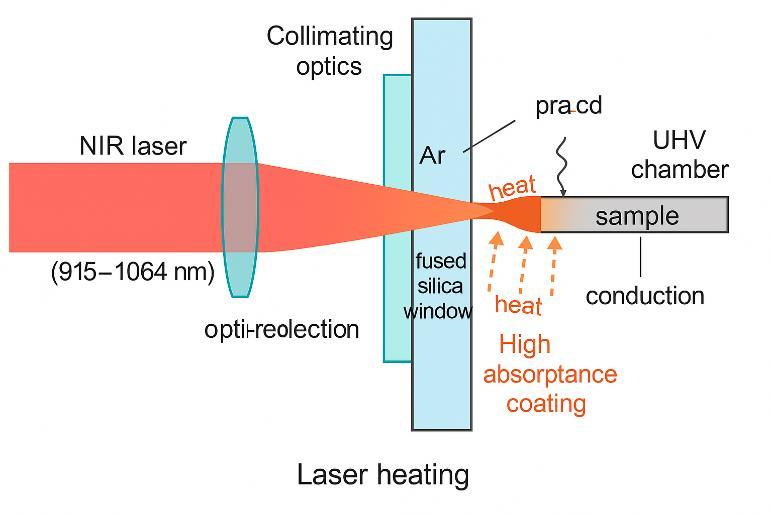
3. Thermal Balance and Laser Power Selection
The laser power absorbed by the sample compensates for radiative loss, conductive loss through supports, and other thermal losses. This can be represented by a simplified heat balance: Pin × α = Prad + Pcond + Pmisc. Here, α is the absorptivity of the back-side absorption layer for the target wavelength band; a reference value is approximately 0.8–0.95.
For a Φ10 mm sample at 600 K target temperature and 300 K ambient, the estimated single-sided radiative loss is approximately 1.5 W, double-sided is about 3 W, and conductive heat through supports ranges from 2 to 3 W. Total net power demand is roughly 5–6 W. Accounting for window losses, beam shaping optics, alignment errors, and absorber inefficiencies, the laser output should be no less than 15 W, with a power adjustment range extending up to 30 W.
For a Φ10×1 mm copper sample, the theoretical heat capacity is approximately 0.11 J/K. With a net heating power of 8 W, the ideal time to raise the temperature from 300 K to 600 K is about 4.1 seconds. In practice, due to conductive heat loss through supports, radiative losses, control speed limits, and structural thermal inertia, the actual heating process typically takes tens of seconds to several minutes.
4. Optical Link and Top-Hat Beam Design
The fiber-output laser is first collimated into a low-divergence beam, then expanded by 8–10× to reduce power density on individual optical elements. It then enters a top-hat beam shaper to convert the Gaussian profile into a uniform energy distribution across the target area. If sample size or position varies significantly, high-speed galvanometer scanning can be used instead to achieve time-averaged homogenization.
The focusing mirror has a reference focal length of approximately 250 mm, generating a spot size matching the Φ10 mm sample at the working distance. The optical layout must accommodate space for the STM chamber, flanges, sample stage, and other instruments, while providing low-power pre-alignment, fine optical axis adjustment, and locking mechanisms. Light baffles and beam traps capture specular reflections and edge scattering to prevent stray light from entering the probe or optical detection channels.
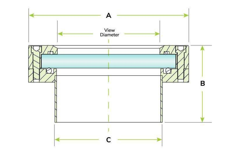
5. Fused Silica Viewport and Vacuum Interface
The system prioritizes CF40 or CF63 fused silica windows with a thickness of approximately 6–10 mm. Fused silica offers excellent transmission in the 0.2–3 μm band, making it suitable for 915, 976, and 1064 nm near-infrared lasers. With double-sided AR coating, single-surface reflectance at the target wavelength can be controlled to approximately 0.3–0.5%. Ordinary glass is recommended only for low-power optical alignment.
The window can be designed with a wedge angle of 0.5–1° to reduce interference and back-reflection caused by parallel surfaces. For higher incident power or long-term operation, the window mount can be configured with water cooling and a temperature sensor. Window temperature is used not only for equipment protection but also to detect beam misalignment, coating contamination, or abnormal reflection.
6. PID Closed-Loop Temperature Control and Multi-Layer Safety Interlocks
The system integrates existing thermocouples or optical pyrometers to feed sample temperature data into an industrial real-time control platform, where a PID algorithm dynamically adjusts laser power. The laser output is equipped with a mechanical reset electric shutter, featuring a typical shutdown time of less than 50 ms. Hardware and software power limiting are implemented, while door magnets, vacuum levels, and viewport temperatures continuously contribute to safety monitoring.
7. Comparison Between External Laser Illumination and Quartz Lamp Focusing Solutions
- Spatial Selectivity: Φ10 mm top-hat spot with sharp boundaries and high uniformity.
- Window heat load: With narrowband transmission, window heat absorption remains low even with 10 W incident power.
- Fine-tuned response: millisecond-level power adjustment for rapid temperature control.
- Low-Temperature Compatibility: Localized heating with minimal background thermal load
8. Installation, Commissioning, and Acceptance Process
- Confirm CF flange, fused silica viewport, AR coating wavelength, and wedge angle orientation; complete vacuum leak test.
- Establish the optical path in low-power safe mode. Align the beam with the window center and sample position using a target card or CCD analyzer.
- Adjust the beam expansion, shaping, and focusing modules to verify the spot size, uniformity, boundary, and power density at the target plane.
- Measure power at the light source, window output, and sample plane to establish a complete transmission efficiency curve.
- Install the absorber layer, heat spreader, and low-thermal-conductivity support; gradually increase power to record the sample's temperature response.
- Tune the PID based on the power–temperature curve, then verify 600 K steady-state operation, over-temperature protection, and shutter shutdown.
- Integrate with STM systems to monitor thermal drift, imaging noise, scattered light, and vacuum stability.
- Establish operating procedures, calibration data, acceptance reports, and abnormal handling workflows.
9. Deliverables and Project Value
Project delivery includes near-infrared lasers, fiber outputs, and power supplies; collimation, beam expansion, shaping, and focusing optical components; fused silica windows with water-cooled mounting structures; sample absorption and homogenization modules; PID temperature control and safety interlock systems; plus installation and commissioning, operation and maintenance manuals, and acceptance test reports.
The core value of this solution is relocating the heat source from inside the ultra-high vacuum chamber to the outside, delivering energy precisely to the sample through an optical window. This achieves localized heating without significantly increasing internal complexity or outgassing load. The system supports STM sample annealing and surface treatment, and can be extended to other in-situ heating experiments sensitive to vacuum cleanliness, vibration, and electromagnetic interference.
Need something similar?
Our technical team delivers customized laser heating solutions tailored to your specific needs.
Contact Us