
Six-zone infrared radiation thermal mechanical fatigue testing furnace
Equipped with 18 short-wave infrared quartz lamp tubes arranged in a ring, this system features six-zone independent PID temperature control to enable rapid infrared heating and thermal cycling of cylindrical specimens. It meets the requirements for thermo-mechanical fatigue testing.
Project Challenges
Performance testing of cylindrical specimens under combined high-temperature and cyclic stress requires rapid heating, precise temperature control, a uniform thermal field, and seamless integration with mechanical test systems.
Use Device
Short-wave infrared quartz lamp tubes (18 × 2 kW), Type S thermocouples, PLC controller, thyristor power regulator, circulating water cooling system, compressed air cooling system
Project Outcomes
Successfully implemented an infrared radiation heating system with independent temperature control for six zones. Features a maximum temperature ≥1300°C and a heating rate ≥50°C/s, meeting the requirements for rapid heating/cooling and precise temperature control in thermo-mechanical fatigue testing.
Case Details
The six-zone thermal engine fatigue high-temperature furnace is designed for high-temperature environment simulation and control. It features a high-temperature heating system and a high-temperature control system that can adjust and maintain the required test conditions. The furnace's control system accepts force signals from external loading systems to coordinate thermal-mechanical fatigue testing, ensuring accurate and reliable performance evaluation of materials under combined high-temperature and cyclic stress conditions.
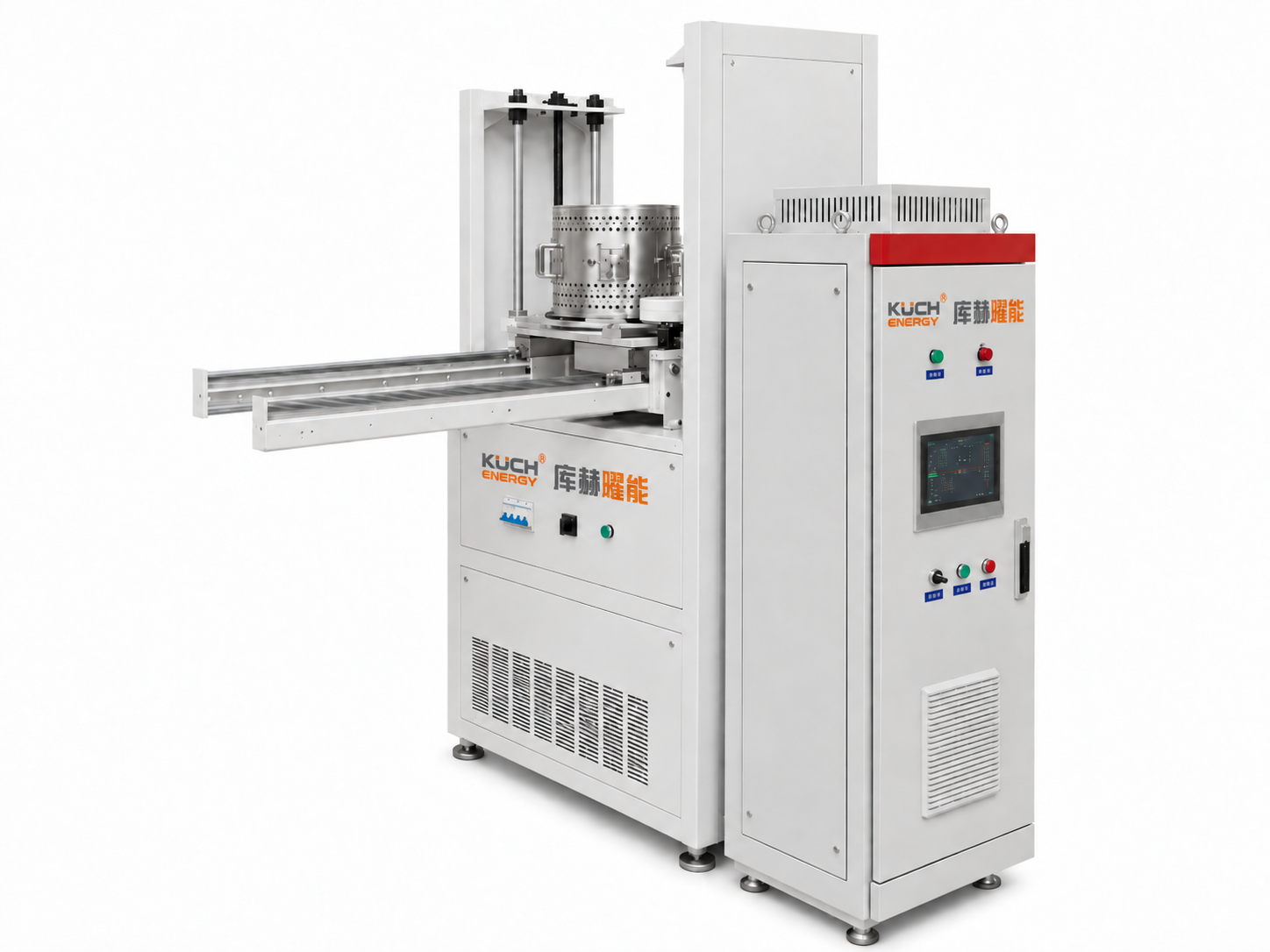
The device features a cylindrical, split-barrel furnace that integrates with a mechanical testing machine via a movable slide table, guide mechanism, and height adjustment structure. When closed, it provides 360° circumferential radiant heating to the specimen's gauge section. Upon opening, the specimen is rapidly exposed, facilitating clamping, observation, forced cooling, and thermomechanical fatigue cycling. Ideal for high-temperature fatigue research in aerospace and energy sectors.
1. System Components
- Cylindrical Split-Top High-Temperature Furnace Body with Mobile Support Mechanism
- 18 Short-wave Infrared Quartz Lamp Tubes with Ceramic Insulated Mounting Assemblies
- 6-Channel S-Type Thermocouple Temperature Measurement Module
- PLC, touchscreen, 6 PID control channels, and 6 thyristor power regulation units
- Furnace shell circulating water cooling system, lamp tube cold-end cooling structure, and flow monitoring unit
- Specimen compressed air forced cooling system
- Loading rod interface with opening, positioning, and safety interlock for use with mechanical testing machines
- Temperature curve, alarms, operating status, and test data logging software
II. Design Objectives
The device provides rapid infrared radiation heating and temperature cycling control for the working section of cylindrical or rod-shaped specimens. The effective heating range shall be at least Φ50 mm × 200 mm, with a maximum temperature of not less than 1300°C. Independent power adjustment across 6 zones minimizes circumferential temperature differences, enabling coordinated thermal-mechanical fatigue testing in conjunction with an external mechanical loading system.
3. 18 Lamp Layout and Six-Zone Temperature Configuration
The 18 lamps are evenly spaced angularly around the furnace circumference, with lamp axes parallel to the sample axis and radiating surfaces facing the sample's working section. Lamps are numbered A1 to A18 in clockwise order to facilitate installation, wiring, commissioning, fault localization, and spare part replacement. Each temperature zone consists of 3 consecutive adjacent lamps, forming a distinct radiation unit with defined circumferential coverage.
| Temperature Zone | Tube ID | Number of Tubes | Rated Power per Zone |
|---|---|---|---|
| Z1 | A1、A2、A3 | 3 | 6 kW |
| Z2 | A4、A5、A6 | 3 | 6 kW |
| Z3 | A7、A8、A9 | 3 | 6 kW |
| Z4 | A10、A11、A12 | 3 | 6 kW |
| Z5 | A13、A14、A15 | 3 | 6 kW |
| Z6 | A16、A17、A18 | 3 | 6 kW |
4. Advantages of Partition Control
- Independent temperature measurement and power control per zone, with automatic compensation for lamp efficiency, reflectivity, and heat dissipation based on actual zone temperatures.
- The six zones can be set to the same target temperature for a uniform thermal field or to different temperatures to create a circumferential temperature gradient.
- Individual temperature zones can be shut down and triggered for alarms independently, without affecting fault localization or maintenance.
- The six-zone load can be distributed across the three-phase power supply in two-zone-per-phase segments to reduce phase imbalance.
V. Key Technical Parameters
| No. | Project | Metric / Description |
|---|---|---|
| 1 | Device Name | Six-zone infrared radiation thermal mechanical fatigue testing furnace |
| 2 | Heating element | Short-wave infrared twin heating tube, 18 pcs |
| 3 | Heating Method | Evenly distributed around the furnace circumference for heating |
| 4 | Rated power per tube | 2 kW |
| 5 | Total Heating Power | 36 kW |
| 6 | Number of heating zones | 6 zone independent temperature control |
| 7 | Single-zone configuration | 3 lamp(s), rated power 6 kW |
| 8 | Effective heating length of the lamp | 200 mm |
| 9 | Target effective heating range | Not less than Φ50 mm × 200 mm |
| 10 | Maximum temperature | ≥1300℃ |
| 11 | Target maximum heating rate | ≥50℃/s |
| 12 | Target maximum cooling rate | ≥50℃/s |
| 13 | Temperature control accuracy | Better than ±4% |
| 14 | Temperature sensor element | Type S thermocouple, 0~1600°C |
| 15 | Control Mode | PLC + HMI + 6 PID loops + 6 silicon-controlled rectifier power control |
| 16 | Run Mode | Single-zone independent, arbitrary combination, six-zone synchronization, program curve operation |
| 17 | Main Power Supply | AC 380 V, 50 Hz, 3-phase, 5-wire |
| 18 | Furnace Structure | Cylindrical half-round, horizontally sliding opening |
| 19 | Insulation material | Mullite Fiber Board Thermal Insulation |
| 20 | Circulating water cooling | Total flow ≥ 3 m³/h, interface DN12 |
| 21 | Sample Cooling | Compressed air blow cooling, PLC-controlled solenoid valve |
| 22 | Security Protection | Over-temperature, thermocouple break, overcurrent, leakage, low water level, low flow rate, gas shortage, limit switch, and emergency stop protection |
6. Structure and Functional Design
The furnace shell is constructed from 304 stainless steel via welding and sheet metal forming, featuring a cylindrical semi-circular split design. The two halves are mounted on a linear guide mechanism for horizontal opening and closing. When closed, they create a sealed radiation space around the specimen; when open, the specimen is fully exposed for easy loading, observation, and rapid cooling. Openings for load rod clearance are provided at the top and bottom of the furnace, with预留 mounting space for integration with the testing machine's grips, pull rods, and extensometers.
Each of the 18 lamps is installed axially parallel and circumferentially evenly spaced. The hot end of each lamp is positioned within the effective heating zone, while the cold end and electrical connection points are located outside the insulation layer, utilizing high-temperature-resistant ceramic insulators, flexible heat-resistant wiring, and a removable clamping structure. A reflective and thermal insulation structure is mounted on the back of each lamp to minimize ineffective heat loss to the furnace shell and enhance radiation utilization toward the sample. Each lamp can be independently removed and reinstalled for easy maintenance.
The furnace chamber uses a low-heat-storage, thermal-shock-resistant composite of alumina/mullite fiber. The insulation layer is stratified by heating lamp, reflector surface, and water-cooled shell to ensure rapid heating response while minimizing outer shell temperature rise. In high-temperature zones, materials prone to crumbling or contaminating samples are avoided. The refractory lining features a modular design for localized replacement when damaged.
7. Six-Zone Temperature and Electrical Control
Each temperature zone is equipped with 1 Type S thermocouples. Thermocouple signals are isolated and acquired by a module, then sent to a PLC/PID controller. The controller compares the measured temperature against the set curve and outputs power adjustment commands to the corresponding thyristor power control unit, which regulates the 3 lamps in that zone. The six loops share an identical structure, operate independently, and are managed centrally via the touchscreen.
- Real-time display of T1–T6 temperatures, setpoints, output power, heating/cooling stages, and operational status
- Supports single-zone settings, group operation, six-zone synchronous running, and multi-segment program curves.
- Supports PID tuning, power limit settings, heating ramp rate limits, and temperature difference compensation.
- Log temperature, power, alarms, interlocks, and test events with export support
- Reserves interfaces for start/stop, synchronous triggering, and status interaction with mechanical testing machines or host computers.
8. Cooling System and Safety Interlocks
The furnace shell, cold ends of the lamp tubes, and areas around the viewing windows are equipped with a circulating water cooling channel. The main loop flow rate must be at least 3 m³/h, with interface pipe diameter DN12. The system monitors inlet/outlet water temperature, flow rate, and pressure. If cooling water is not established, flow is insufficient, or outlet temperature exceeds limits, the control system will prevent heating startup or immediately cut off all heating output.
The specimen is cooled by compressed air blowdown. The PLC controls the solenoid valve timing, blow sequence, and duration according to the program curve, with interlocks for furnace startup, mechanical loading status, and temperature conditions. Nozzle positions must be adjustable to ensure uniform cooling of the specimen's gauge section and prevent direct impingement on thermocouples and fixtures.
- Over-temperature, temperature difference limit breach, thermocouple breakage, and sensor anomaly protection
- Tube circuit overcurrent, short-circuit, leakage, and thyristor overheating protection
- Low water, low flow, high cooling water temperature, and air shortage protection
- Furnace door open/close position, slide table limit switches, test machine status, and emergency stop interlock
- Control cabinet audio-visual alarm, fault logging, and safe reset after power loss
IX. Typical Test Procedures
- Retract the furnace from the loading zone to complete installation of the specimen, fixture, thermocouple, and mechanical loading system.
- Check status of circulating water, compressed air, power supply, emergency stop, and furnace limit switches.
- Push the furnace into place and align it. Close the left and right halves, then verify that the loading rod does not interfere with the furnace body.
- Set six-zone target temperature, heating rate, holding time, mechanical loading sync point, and cooling program on the touchscreen.
- Start the circulating water cooling system. After interlock confirmation, engage Zone 6 heating; the system will automatically perform temperature difference compensation.
- After reaching the specified temperature and stable conditions, send a synchronization signal to the mechanical testing machine or receive a loading trigger signal.
- Execute the heating–loading–soaking–unloading–gas-blowing cooling cycle per the test procedure.
- After the test, save and export the six-zone temperature, power, alarm, and event logs. Open the furnace once the temperature drops to a safe level.
10. Project Summary
This project proposes building a six-zone infrared radiation thermal-mechanical fatigue test furnace. It utilizes 18 ring-distributed 2 kW quartz lamps, with every 3 lamps forming 1 independent heating zones to create a total of 6 temperature zones and a combined heating power of 36 kW. The system is equipped with 6 Type S thermocouples, a PLC, 6 PID control loops, and 6 thyristor power control units. It supports independent temperature control for each zone, synchronized operation, temperature difference compensation, program curve control, data logging, and alarm management. Combined with a semi-circular split furnace body, circulating water cooling, compressed air cooling, and an interface linked to the mechanical testing machine, it meets the requirements for rapid heating, soaking, mechanical loading, and rapid cooling in thermal-mechanical fatigue tests.
Need something similar?
Our technical team delivers customized laser heating solutions tailored to your specific needs.
Contact Us