
Single-sided radiant heating system with silicon-carbon rods inside a transparent ceramic vacuum chamber
Utilizes a vacuum chamber with a silicon-carbon rod array and high-purity SiC heat distribution plate, featuring three independently controlled zones to achieve single-sided radiant heating of 90 mm × 200 mm transparent ceramic samples at 1200℃. Meets low-pressure oxygen atmosphere process requirements.
Project Challenges
The transparent ceramic rectangular sample requires high-temperature processing at 1200°C under vacuum or low-pressure oxygen conditions. The temperature must be uniform across the 90 mm × 200 mm area, with a rapid heating rate of 30°C/min, while ensuring safe switching between cold-state high vacuum and low-pressure oxygen environments.
Use Device
Silicon-carbon rod array (6 straight rods or 3 U-shaped rod sets), high-purity dense SiC heat distribution plate (120×230×5~6 mm), three-zone independent SCR power control system, S-type thermocouple multi-point temperature measurement, and dual-path vacuum system with molecular pump + dry mechanical pump.
Project Outcomes
Successfully designed a three-zone independent heating system using silicon-carbon rods combined with single-sided radiation heating from a high-purity SiC hot plate. Total installed capacity: 12–15 kW. Achieves target temperature of 1200°C, heating rate of 30°C/min, and 1-hour low-pressure oxygen holding time, with steady-state uniformity within ±15°C.
Case Details
This solution addresses high-temperature processing of rectangular transparent ceramic samples under vacuum or low-pressure oxygen conditions. It features active heating via silicon-carbon rods inside a vacuum chamber, secondary heat distribution using a high-purity dense silicon carbide plate, and single-sided radiant heating for the sample. The design focuses on achieving uniform temperature across a 90 mm × 200 mm effective area, ramping at 30 °C/min, holding at 1200 °C for 1 hours, and enabling seamless switching between cold-state high vacuum and low-pressure oxygen environments.
For the cold start, pump down to approximately 0.001 Pa, isolate the molecular pump, and backfill with process gas to around 5 Pa before initiating heating. Ramp the sample at 30 °C/min to 1200 °C. During the soak phase, gradually introduce oxygen while increasing pressure to 100 Pa. In the high-temperature stage, a dry mechanical pump with a throttle valve maintains pressure; the molecular pump does not directly handle continuous pumping in the 5–100 Pa atmosphere range.
I. Design Inputs and Target Metrics
| Project | Design Requirements / Recommended Values |
|---|---|
| Heat object | Transparent ceramic rectangular sample |
| Valid Sample Area | Approx. 90 mm × 200 mm |
| Heating Method | Vacuum chamber interior, single-sided radiant heating |
| Maximum sample temperature | 1200 ℃ |
| Heating rate | 30 ℃/min, from room temperature to 1200 ℃ |
| Insulation time | 1200 for 1 hours |
| Cold-state ultimate vacuum | Approx. 0.001 Pa |
| Heating Startup Pressure | Approx. 5 Pa |
| insulating atmosphere | Gradually introduce oxygen until pressure reaches 100 Pa. |
| Suggest steady-state uniformity targets | Within 90 mm × 200 mm area: ±15 ℃, after tuning and optimization |
| Recommended central temperature stability | Steady state: ≤±2 °C, measured at the sample or heat spreader's control point. |
II. Overall Technical Approach
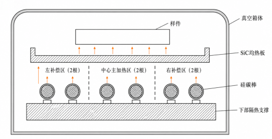
We recommend a modular chamber structure featuring a silicon-carbon rod array, a high-purity SiC heat-distribution plate, and three independently controlled heating zones. The silicon-carbon rods serve as the high-temperature radiation source. The high-purity SiC plate absorbs this radiation and, leveraging its superior thermal conductivity, flattens the strip-shaped thermal field to deliver a continuous rectangular temperature profile to the transparent ceramic samples.
- Silicon-carbon rods span the short side of the equalizing plate and are arranged along the 230 mm length to minimize temperature variation across the width.
- Divide the length into a left compensation zone, a central main heating zone, and a right compensation zone, with independent power control for each zone.
- The heat spreader dimensions exceed the sample's active area, with 10–15 mm of radiation margin on all sides to reduce edge temperature.
- Install multi-layer radiation shields on the back and shallow baffles on both sides to minimize unnecessary radiation to the vacuum chamber's cold walls.
- Thermocouples and over-temperature protection are configured independently for silicon-carbon rods, soaking plates, and samples to avoid reliance on single-point temperature control.
III. Heating Module Structural Design
3.1 Silicon Carbon Rod Array
We recommend using 6 straight-type silicon carbide rods of small diameter, or 3 sets of equivalent U-shaped silicon carbide rods. The effective heating section spans approximately 120 mm across the short side of the uniform heating plate, with every two rods forming an independent control zone. This arrangement allows for separate power compensation at both ends along the 230 mm length direction and facilitates future grouping by resistance value and single-zone maintenance.
| Project | Recommended Configuration |
|---|---|
| Component Form | Straight or U-shaped small-diameter silicon carbide heating elements |
| Suggested Quantity | 6 straight bars, or 3 U-bar sets |
| Suggested Diameter | Approx. 8–12 mm, subject to supplier specifications |
| Effective heating coverage | Span across the short side of the heat pipe with a coverage width of at least 120 mm. |
| Center-to-center distance | Recommended to be at least 2.5–3 times the rod diameter. |
| Bar-to-Heat Pipe Distance | 20~30 mm, with adjustable structure |
| Expected Normal Rod Temperature | Approximately 1300–1450 °C, subject to actual measurements and manufacturer specifications. |
| Power Supply Mode | Low-voltage, high-current transformer + SCR continuous power control |
3.2 High-Purity SiC Vapor Chamber
Vapor chambers should primarily use high-purity, dense, pressureless-sintered silicon carbide (SiC). Conventional reaction-bonded SiC with high free silicon content is not recommended. Vapor chambers serve only for heat absorption, distribution, and radiation; they cannot function as electrical insulators. Positioning, support, and electrode insulation remain provided by high-purity alumina.
| Project | Recommended Configuration |
|---|---|
| Materials | High-purity dense SiC |
| Suggested size | 120 mm × 230 mm |
| Recommended thickness | 5–6 mm |
| Distance from Sample | 8–15 mm |
| Installation Method | Three or four-point floating support |
| Thermal expansion allowance | Leave a margin of 1~2 mm or more in the length direction. |
| Surface Condition | Clean, free of organic coatings; finish by fine grinding or fine sandblasting |
| Temperature Measurement Layout | Center, left end, and right end require at least 3 points; 5 points are recommended during the debug phase. |
3.3 Back Radiation Shield and Support Structure
The back of the silicon carbide rod is equipped with 2 to 3 layers of thin radiative screens, separated by high-purity alumina sleeves to reduce radiative heat loss to the vacuum chamber's water-cooled walls. The silicon carbide rods, SiC homogenization plates, and radiative screens must be allowed free thermal expansion; rigid clamping structures are prohibited. Avoid using standard ceramic fiber boards with binders, standard black coatings, or outgassing-prone organic materials inside the chamber.
IV. Soaking Design and Control Strategy
4.1 Independent power control for Zone 3
The primary temperature gradient in the 90 mm × 200 mm area typically occurs at both ends along the length and along all four edges. We recommend dividing the 6 silicon-carbon rods into three zones (left, center, right) with pairs of rods per zone. Each zone should be equipped with its own transformer, SCR power controller, current transformer, and independent temperature compensation.
| Control Area | Recommended Initial Installed Power | Initial Power Ratio | Primary Function |
|---|---|---|---|
| Left Compensation Zone | 4.0–5.0 kW | 105%~115% | Compensate for left-side and edge heat dissipation |
| Central Main Heating Zone | 3.5–4.5 kW | 100% | Maintain and sustain body temperature |
| Right-side compensation zone | 4.0–5.0 kW | 105%~115% | Compensate for right-side and edge heat dissipation |
Recommended total installed capacity: 12–15 kW. A higher capacity margin at the ends does not imply continuous high-power operation; actual output is automatically adjusted based on multi-point temperature readings.
4.2 Rod-plate distance and uniformity
If the distance between the silicon carbide rod and the heat distribution plate is too small, distinct striped hot spots will appear on the plate's surface; if it is too large, radiation efficiency drops. We recommend designing the rod-to-plate distance at 20–30 mm with adjustable mounting holes to allow optimization within approximately 15–35 mm during prototype tuning. Maintain parallelism between the heat distribution plate and the silicon carbide rod array within ±1 mm.
4.3 Resistance Binning and Aging Compensation
- Silicon carbon rods within the same zone shall be of the same batch and have similar cold-state resistance values.
- Independent monitoring of voltage, current, and actual power per zone to prevent uneven power distribution in parallel rods.
- The power supply must have sufficient voltage headroom to accommodate the resistance increase in silicon-carbon rods after aging.
- Do not mix new rods with severely aged ones in the same area.
- Periodically record voltage, current, and thermal field data for each zone to assess component aging.
5. Vacuum and Oxygen Process Control
To ensure molecular pump safety, protect the silicon-carbon rod surface, and maintain process repeatability, the vacuum system should separate the high-vacuum line from the process-pressure line. Use the molecular pump for cold pumping to high vacuum. Before entering the 5–100 Pa process stage, close the high-vacuum valve and isolate the molecular pump; maintain pressure using a dry mechanical pump with a throttling valve.
| Process Phase | Stress/Atmosphere | Molecular Pump Status | Heating | Control Instructions |
|---|---|---|---|---|
| Cold vacuum | Pumped to 0.001 Pa | Enable | Close | Complete initial outgassing of the chamber and materials |
| Ready for backfill | Fill back to 5 Pa | Isolate | Close | Use dry oxygen or oxygen-containing gas |
| Warming-up phase | Starting at 5 Pa, 30 ℃/min | Isolate | Enable | Gradually increase oxygen pressure as temperature rises for greater safety. |
| Keep at 1200 ℃ | Oxygen gradually increases to 100 Pa. | Isolate | Insulated Closed Loop | Soak for 1 hours; control pressure according to the process curve. |
| Cooling phase | Maintain process atmosphere or evacuate as required | Isolate | Close | Avoid sudden transition to high vacuum while in a high-temperature state. |
| Restore High Vacuum | After the temperature drops to a safe level | Restart | Close | Pump down to ultra-high vacuum again |
If the backfill gas is an oxygen-free gas such as argon or nitrogen at 5 Pa, the silicon carbon rod will operate in a high-temperature, low-oxygen environment during the final heating stage, reducing the stability of its surface protective film. We recommend pre-oxidizing the silicon carbon rod with clean, dry air before installation and introducing oxygen before reaching 800–1000 °C. If the process does not allow early oxygen introduction, acceptability must be verified through prototype life testing.
6. Temperature Measurement and Closed-Loop Control
| Temperature Measurement Location | Suggested Quantity | Function |
|---|---|---|
| Left end of the SiC heat spreader | 1 o'clock | Control Left Compensation Zone |
| SiC Heat Spreader Center | 1 o'clock | Main Ramp-Up Curve and Total Power Control |
| Right end of the SiC heat spreader | 1 o'clock | Control right compensation zone |
| Center of the heated surface of the sample | 1 o'clock | Process Temperature Calibration or Master Control |
| Center of the back of the sample | 1 o'clock | Monitor thickness-direction temperature difference |
| Silicon Carbon Rod Equivalent Temperature | At least 1 points/regions or unified protection points | Barrel Overtemperature Interlock |
The primary temperature measurement should use Type S thermocouples with high-purity alumina dual-bore insulating tubes. During initial commissioning, add 5 or 9 temporary temperature measurement points in the soaking zone's effective area to adjust bar spacing, bar-to-plate distance, and power ratios across zones. If transparent ceramics are used for infrared pyrometry, verify the material's transmittance and emissivity at the selected wavelength band first; do not use it as a primary control signal without calibration.
VII. Electrical System and Safety Interlocks
- Three independent low-voltage high-current isolation transformers, with single-zone power rated at approximately 4 to 5 kW.
- Three-phase SCR continuous power control with soft start, current limiting, and true RMS current detection
- The vacuum-introduced electrode utilizes a low-voltage, high-current design. Internal conductors must avoid sharp corners, burrs, and insufficient electrical clearances.
- Set interlocks for heat spreader overtemperature, silicon carbon rod overtemperature, vacuum pressure anomaly, oxygen pressure anomaly, cooling water anomaly, and cabinet overcurrent.
- Do not enable high-power heating if the pressure is outside the allowable range or if the molecular pump high-vacuum valve is not closed.
- All cables, seals, and connectors in oxygen service must be made of clean materials compatible with pure oxygen.
8. Recommended Control Parameters
| Manage Project | Suggested Settings |
|---|---|
| Sample heating rate | 30 °C/min |
| Maximum Sample Temperature | 1200 ℃ |
| Normal operating temperature of the vapor chamber | Approx. 1220~1280 °C; actual heat transfer conditions apply |
| Normal operating temperature of silicon carbide heating rod | Keep within the range of 1300 to 1450 °C. |
| Over-temperature protection for silicon-carbon rods | Set based on manufacturer-specified values for components; do not rely solely on temperature estimates from samples. |
| Vapor Chamber Effective Zone Uniformity Target | Steady state: ≤±15 °C, confirmed after commissioning. |
| Sample Center Temperature Control Stability | Steady state: ≤ ±2 ℃ |
| Heating Startup Pressure | Approx. 5 Pa |
| Insulated Oxygen Pressure | Gradually increase pressure to 100 Pa over 1 hours according to the process |
| Installed power | 12–15 kW |
IX. Materials and Key Configuration Recommendations
| Component | Recommended Materials/Configurations | Instructions |
|---|---|---|
| Silicon Carbon Rod | High-temperature SiC heating elements, batch-matched. | Supplier must confirm the operating boundary under 5~100 Pa atmosphere. |
| Vapor Chamber | High-purity dense SiC, 120×230×5~6 mm | Floating installation, no organic coating |
| Insulated Stand | ≥99.7% High-Purity Alumina | Insulation support for electrodes, rods, and soaking plates |
| Back radiation shield | Oxidation-resistant high-temperature thin sheets, arranged in multiple spaced layers | Do not come into direct contact with silicon carbide rods. |
| Thermocouple | S-type thermocouple + high-purity alumina protection tube | Multi-point temperature measurement |
| Vacuum Electrode | Low-voltage high-current water-cooled or high-temperature insulated electrode | Three-zone independent import |
| Power System | Isolation transformer + SCR + current closed-loop | Reserve capacity for aging lift-drag compensation |
| Vacuum System | Molecular pump high-vacuum branch + dry pump process branch | Isolate the molecular pump at 5~100 Pa stage |
10. Debugging and Acceptance Recommendations
- Complete the in-vacuum module cleaning, drying, and vacuum degassing under no-load conditions. Record the cold-state ultimate vacuum and the outgassing curve during temperature rise.
- Heat up under no load from 10 to 15 °C/min to 800 °C, then check the current in each zone, rod condition, and temperature difference across the soaking plate.
- Increase the heating rate to 30 °C/min and record the hot plate temperature at 5 or 9 points at 800 °C, 1000 °C, and 1200 °C.
- Adjust the rod-to-plate distance, end power ratio, and three-zone PID parameters to achieve the specified temperature difference for the 90 mm × 200 mm region.
- After installing the transparent ceramic sample, recalibrate the center, edge, and back temperatures of the sample. Verify the temperature gradient across the thickness and check for thermal deformation.
- Perform at least 3 complete cycles under an initial pressure of 5 Pa and oxygen holding conditions of 100 Pa. Check for changes in the silicon-carbon rod resistance, the surface condition of the heat distribution plate, and surface deposition on the sample.
- Record temperature rise curve, thermal stability, zone uniformity, vacuum/pressure curve, voltage/current, and safety interlock actions during acceptance testing.
11. Technical Risks and Scope Limitations
- The service life of silicon-carbon rods under low oxygen partial pressure and high-temperature conditions depends closely on the actual gas composition. A total pressure of 5 Pa cannot replace oxygen partial pressure; the backfill gas must be specified.
- Sample: The SiC rod temperature at 1200 °C is typically higher than 1200 °C. The final allowable temperature must be confirmed by the SiC rod supplier based on the specific model.
- Silicon-carbon rods experience resistance increase over time; equipment must maintain voltage compensation capability and establish a component aging log.
- Spectral absorption, thickness, thermal conductivity, and surface condition of transparent ceramics affect the actual heating power and temperature difference between the front and back surfaces.
- Surface conditions of SiC plates in low-pressure oxygen may change with cycling; the most adverse atmosphere cycle validation must be performed prior to formal delivery.
- The power, spacing, and temperature ranges provided in this proposal are initial engineering design values. Final parameters must be validated through thermal simulation, supplier confirmation, and prototype testing.
XII. Conclusion
Based on temperature uniformity, chamber dimensions, vacuum/oxygen switching requirements, and heating rate specifications, we recommend a single-sided radiant heating configuration featuring 6 independent three-zone SiC rod heaters, a high-purity SiC heat spreader of 120 mm × 230 mm, multi-layer backside radiation shields, and multi-point closed-loop temperature sensing. Total installed power is recommended at 12–15 kW. The distance from the SiC rods to the heat spreader should be 20–30 mm, and the distance from the heat spreader to the sample should be 8–15 mm. For cold start, use a molecular pump to evacuate to 0.001 Pa. Before heating, isolate the molecular pump and backfill to 5 Pa; maintain pressure during heating and soaking stages using dry mechanical pumps and throttling valves.
This solution has the engineering capability to achieve sample heating at 1200 °C, 30 °C/min ramp rate, and 1 hours of low-pressure oxygen annealing. Final uniformity and component lifespan depend on the actual gas composition during the 5 Pa stage, the allowable temperature of SiC heating elements, the spacing of the heat distribution plate installation, and the results of three-zone tuning. We recommend completing no fewer than 3 full process cycle validations prior to formal production.
Need something similar?
Our technical team delivers customized laser heating solutions tailored to your specific needs.
Contact Us