
3 kW Mobile Laser Heat Flux Loading System
Uses a 3 kW/980 nm laser beam, expanded and homogenized with square-spot shaping, to deliver an average incident heat flux on the order of 200 kW/m² over a 100 mm × 100 mm working area. Supports both closed-loop temperature control and heat flux control modes. Features a mobile, all-in-one design with a maximum input power of ≤8 kW.
Project Challenges
Under a maximum total input power constraint of ≤8 kW, achieve rapid, adjustable, and repeatable non-contact heating with an average incident heat flux in the 200 kW/m² range over a 100 mm × 100 mm test area. The solution must account for variations in material absorptivity, protect against soot contamination, and support deployment across multiple test platforms.
Use Device
3 kW/980 nm high-efficiency laser, beam expansion and homogenization module with square spot shaping, infrared thermometer, heat flux calibration and material absorptivity conversion module, integrated air-cooled chiller, side-draft fume extraction system, PLC + touchscreen control system
Project Outcomes
Develop a mobile integrated laser thermal loading solution: effective incident optical power on the working surface ≥ 2.0 kW, square quasi-flat-top beam uniformity ≤ ±10%, dual-mode control with temperature closed-loop and incident heat flux regulation, supported by heat flux calibration and material absorptivity correction. Total internal system power consumption ≤ 7.5 kW.
Case Details
This project builds a 3 kW mobile laser heat flux loading system to deliver rapid, adjustable, and repeatable non-contact radiative heating to a 100 mm × 100 mm test area. Using a high-power laser as the heat source, the system employs collimation, beam expansion, homogenization, and square beam shaping to uniformly project laser energy onto the specimen surface, achieving a target incident heat flux of 200 kW/m² (defined as the average incident laser heat flux on the target working plane).
Accounting for differences in energy absorption rates across materials at the same laser wavelength, the system software includes thermal flux calibration and material absorptivity correction. Based on user-defined absorptivity coefficients, it converts incident heat flux at the work surface into absorbed heat flux on the sample surface. To address potential soot, volatiles, and particulate contamination during heating, the system features a local exhaust fan and optical window protection, venting contaminants to the outdoors via ducts.
1. Design Basis and General Technical Requirements
| No. | Project | Technical Requirements |
|---|---|---|
| 1 | Heating Method | Laser non-contact radiative heating |
| 2 | Rated Optical Output Power of the Laser | 3 kW |
| 3 | Laser operating wavelength | 980 nm |
| 4 | Target heating zone | 100 mm × 100 mm |
| 5 | Target average incident heat flux | 200 kW/m² |
| 6 | Effective incident optical power at the work surface | ≥2.0 kW (at rated heat flux) |
| 7 | Spotlight Mode | Square, flat-top |
| 8 | Uniform Heating | Target accuracy within the 100 mm × 100 mm effective area: ≤±10%, subject to optical simulation and actual calibration results. |
| 9 | Control Mode | Temperature closed-loop control / incident heat flux control; Heat flux mode supports material absorptivity correction and absorbed heat flux conversion |
| 10 | Temperature Feedback | Primary device: Infrared thermometer. Ensure the measurement wavelength avoids the 980 nm laser band. An infrared thermal imager is available as an optional accessory. |
| 11 | Smoke and Dust Treatment | Local side-draft fan extraction vents through a flue pipe to the outdoors, preventing airflow from directly sweeping across the test specimen surface. |
| 12 | Cooling Method | Closed-loop water cooling for laser and necessary optical components |
| 13 | Device Form | Mobile Integrated Unit |
| 14 | Power | AC 380 V, 50 Hz, Three-Phase Five-Wire |
| 15 | Maximum Input Power (Whole Unit) | ≤8 kW |
| 16 | Security Protection | High-power laser local shielding, multi-level interlocks, emergency stop |
II. Key Parameter Calculation and Power Matching
The target average incident laser heat flux is 200 kW/m², with a heating area of 100 mm × 100 mm (0.01 m²). The effective incident laser power required to achieve this heat flux on the work surface is P = q × A = 200 kW/m² × 0.01 m² = 2.0 kW. Thus, when the work surface effectively receives an average laser power of 2.0 kW, the theoretical average incident laser heat flux is 200 kW/m².
Laser power transmitted from the source to the target workpiece undergoes collimation, beam expansion, homogenization, shaping, and passage through a protective window, incurring optical losses. With a system transmission efficiency designed between 75% and 85%, a rated output power of 3 kW delivers approximately 2.25 to 2.55 kW of effective power at the workpiece (yielding ~225 kW/m² at η=75%). This meets the design requirement of 200 kW/m² while maintaining margins for optical losses, control headroom, and long-term operational reliability.
For material heat flux conversion, the system correlates the incident heat flux density q_inc at the work surface (obtained from heat flux meter calibration) with the user-entered material absorptivity coefficient α. The equivalent absorbed heat flux density on the sample surface is calculated as q_abs = α × q_inc. If the user directly sets a target absorbed heat flux q_abs,set, the software calculates the required incident heat flux as q_inc,set = q_abs,set / α and generates the corresponding laser power command based on the calibration curve. This conversion is a model calculation based on calibration results and user-provided absorptivity data, not a direct measurement of absorbed heat flux at the sample surface.
3. System Overview
- Laser Heat Source Module: 3 kW/980 nm high-efficiency laser with external analog/digital power control support
- Beam Shaping and Homogenization Module: Collimation, Beam Expansion, Integrating Homogenization / Microlens Arrays, and Square Beam Shaping
- Mobile Mechanical Platform: Low-profile Wide-body Integrated Main Cabinet, Lifting Column, and Horizontal Adjustment Mechanism
- Temperature Measurement Module: Primary infrared thermometer; optional infrared thermal imager for temperature field monitoring.
- Heat Flux Calibration and Power Monitoring Module: Establishes the "Control Command–Incident Heat Flux" calibration relationship using a calibrated heat flux meter.
- Material Absorption Rate Database & Conversion Module: Material Library Management and Real-Time Heat Flux Conversion
- Cooling System: Integrated Air-Cooled Industrial Chiller, Closed-Loop Water Cooling
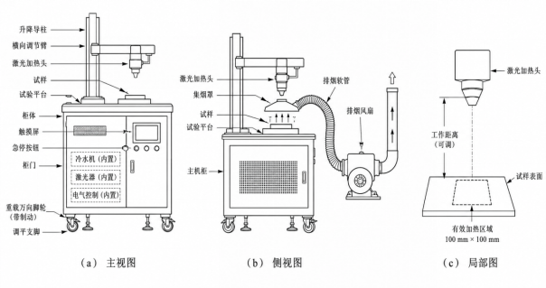
- Exhaust system: Local extraction from the upper side, connected to an exhaust fan via a heat-resistant hose for discharge to the outdoors.
- Electrical Control and Laser Safety System: PLC + HMI, Multi-Level Interlocks, and Emergency Stop
The fume extraction, circulating water cooling, and local laser protection subsystems operate as auxiliary systems linked to the main control unit. The fume extraction status is integrated into the system interlock logic; for tests generating smoke or volatiles, laser activation is prohibited unless the fume extraction system is active.
4. Laser Heat Source and Square Uniform Beam Design
Since the total system's maximum input power is limited to 8 kW, the laser must not only meet the rated optical output of 3 kW but also prioritize electro-optical conversion efficiency, full-power electrical input, cooling load, and external control interfaces. We will select high-efficiency industrial semiconductor lasers, using the actual electrical input power required for continuous 3 kW output as the key selection constraint.
This project is not for cutting or welding. The key objective is not to achieve a minimal focal spot, but to stably expand and homogenize the 3 kW laser into an approximately flat-top beam of 100 mm × 100 mm on the target surface. Recommended optical paths include collimation, beam expansion, integrator homogenization/microlens arrays, or other high-power-compatible homogenization structures, followed by imaging or freeform shaping to create a square working area. Optical design must also account for damage thresholds of high-power components, coating absorption, thermal drift, protective window contamination, and installation misalignment.
Uniformity over the 100 mm × 100 mm active area is specified in terms of incident irradiance/heat flux distribution across the work surface, not directly as sample temperature uniformity. Sample temperature uniformity is also influenced by material thermal conductivity, thickness, fixture heat dissipation, edge effects, and variations in surface absorptivity. During the formal design phase, rated working distance and allowable tolerances are determined through optical simulation and empirical calibration.
5. Dual-Mode Control: Temperature Closed-Loop and Incident Heat Flux
The temperature closed-loop control mode targets the sample temperature. An infrared thermometer continuously acquires the surface temperature of the sample. The controller adjusts the laser output power using PID or feedforward-enhanced PID algorithms based on the deviation between the set and measured temperatures to achieve heating, holding, and programmed temperature control. The infrared measurement system avoids the 980 nm laser band by employing narrowband filtering or spectral isolation measures to minimize interference from reflected laser light on the temperature readings.
- Target Temperature, Heating Rate, Soak Time
- Power limit, over-temperature alarm, and laser shut-off
- Temperature, Laser Power, and Time Curve Logs
The incident heat flux control mode targets the average incident laser heat flux density on the working surface. During commissioning, actual incident power/heat flux under various laser power commands is calibrated at the specified working distance and 100 mm × 100 mm target area using a calibrated water-cooled calorimeter, calorimetric device, or high-power laser power measurement system. This establishes the relationship between "control command," "output optical power," and "average incident heat flux density" on the working surface. During formal testing, this calibration curve is applied alongside power feedback correction to achieve incident heat flux control based on the "heat flux calibration model + power feedback."
The two control modes operate exclusively. In temperature mode, the primary feedback is temperature, with incident heat flux/power as a safety limit. In heat flux mode, the setpoint can be either target incident heat flux or target equivalent absorbed heat flux. Regardless of the mode, safety interlocks always have the highest priority.
VI. Heat Flux Calibration and Material Absorptivity Correction
The system software features a dedicated "Heat Flux Calibration / Material Parameters" page. During calibration, a calibrated heat flux sensor is positioned on the 100 mm × 100 mm target work surface. Heat flux measurements are taken at multiple typical locations; if necessary, a grid-based multi-point measurement approach is used to map the heat flux distribution across the work surface. The average incident heat flux density for the target area is calculated in conjunction with beam uniformity results. Additionally, the system applies stepwise loads under varying laser powers or control commands to establish the calibration relationship.
| Material Library Fields | Instructions |
|---|---|
| Material Name | Test Material Label |
| Surface Condition | Roughness, coating, and other status descriptions |
| absorption coefficient | Effective parameters adapted to surface state, temperature, and angle of incidence at a 980 nm wavelength (0 < α ≤ 1) |
| Operating temperature range | Temperature range for parameters |
| Notes | Multiple parameter versions can be created for the same material in different states. |
After selecting the corresponding material during testing, the software automatically multiplies the calibrated incident heat flux by the material's absorptivity coefficient to calculate the equivalent absorbed heat flux on the sample surface. It simultaneously records the incident heat flux, absorbed heat flux, laser power, and test duration.
VII. Smoke Exhaust and Optical Pollution Protection
The exhaust system uses a side-top local extraction method, positioning the fume hood or intake port without obstructing the main laser beam path or the temperature measurement field of view. The exhaust duct connects to the exhaust fan via a heat-resistant flexible hose. The fan creates negative pressure to draw away smoke, volatile compounds, and particulates generated during heating through the duct and vent them directly outdoors. The exhaust airflow is adjustable; the preliminary design range is approximately 250~400 m³/h, with final adjustments made based on smoke volume, duct length, and on-site ventilation conditions.
Position the sampling port as close to the smoke generation area as possible, without allowing high-velocity airflow to directly impinge on the heated surface of the test specimen. This minimizes convective heat loss and preserves the thermal boundary conditions of the test. The end protection window features a replaceable design and can be equipped with a low-flow clean air curtain to prevent soot accumulation on the lens. The air curtain must not directly blow onto the heated surface of the specimen. The control system supports settings for cumulative operating time or transmission rate maintenance alerts.
8. Mobile Mechanical Structure Design
The equipment features a low-profile, wide-body integrated mobile cabinet. The test platform and samples are mounted on the top surface, while the laser, chiller, electrical control system, and auxiliary components are integrated within the cabinet. A vertical lifting column and horizontal adjustment mechanism are installed at the rear, positioning the laser heating head above the sample for precise height and lateral adjustments. This design lowers the machine's center of gravity, enhancing mobility, positioning accuracy, and operational stability.
- Bottom: 4 industrial heavy-duty casters for easy manual transport in workshops.
- Caster wheels with braking function, plus adjustable leveling feet for stable and secure floor contact during operation.
- The laser beam alignment mechanism features mechanical locking and a working distance reference to prevent positional drift.
- Laser output port, smoke extraction hose, temperature measurement assembly, and cable feature quick-connect interfaces for easy station switching.
- Lower the center of gravity by positioning the laser and chiller at the bottom to improve mobility and operational stability.
9. Total system power budget ≤ 8 kW
The maximum system input power ≤ 8 kW is a key boundary condition for this project. The proposed solution targets a total full-load input power of ≤ 8 kW, with an internal design goal of ≤ 7.5 kW. This approach avoids designing at the theoretical limit near 8 kW, ensuring sufficient margin for component power fluctuations and long-term operation.
| Power Unit | Preliminary power range selection | Instructions |
|---|---|---|
| 3 kW laser | Approx. 5.2–5.8 kW | Prioritize high electro-optical efficiency laser sources |
| Circulating Chiller | Approx. 1.0–1.4 kW | Meets the actual heat dissipation load of laser systems and optical components. |
| Smoke Extraction System | ≤0.35 kW | Variable-speed, low-power exhaust fan that vents smoke and fumes outdoors via ductwork. |
| Control System / Temperature Measurement / Sensors | ≤0.25 kW | PLC, Touchscreen, Temperature Measurement, and Data Acquisition |
| Auxiliary power | ≤0.15 kW | Air curtain, solenoid valve, indicator, etc. |
| Overall System Design Objectives | ≤7.5 kW | The actual power under the most unfavorable full-load test must not exceed 8 kW. |
10. Electrical Control, Data Acquisition, and Safety Interlocks
The control system combines a PLC/industrial controller with a touchscreen HMI. The interface centralizes functions for selecting operating modes, setting target temperature/incident heat flux/absorbed heat flux, managing material selection and absorptance coefficients, generating and retrieving heat flux calibration curves, limiting laser power, defining test duration and cycle counts, displaying alarms, and showing trend graphs. Test data can be saved by timestamp and exported; material parameters and heat flux calibration data support independent saving, retrieval, and updates.
- E-Stop Interlock: Deactivates laser enable immediately upon any E-Stop trigger.
- Laser Safety Interlock: High-power laser output is disabled when the enclosure or safety door is not closed.
- Cooling Interlock: Laser disabled or cut off if water flow is insufficient, temperature is too high, or liquid level is abnormal.
- Smoke Exhaust Interlock: Laser loading is prohibited when smoke exhaust has not started during tests that generate fumes or volatiles.
- Over-Temperature Protection: Rapidly reduces power or shuts off the laser when sample temperature exceeds the set safety limit.
- Power/Heat Flux Overload Protection: Limits power or shuts down immediately when the actual value exceeds the upper limit.
- Enter safe state on errors such as laser failure, communication faults, or sensor malfunction.
- Laser output is disabled while the device is in motion. Before operation, ensure caster brakes are locked, support feet are deployed, and the optical path is verified.
11. Human-Machine Interface (HMI) Functions
| Feature Modules | Main Content |
|---|---|
| Status | Laser Status, Cooling Status, Fume Extraction Status, Safety Interlock Status |
| Temperature Mode | Target temperature, heating rate, hold time, PID parameters, power limit |
| Heat Flow Mode | Target incident heat flux / target absorbed heat flux, material selection, loading time, heat flux slope, power limit |
| Heat flux calibration | Calibration Point Setup, Heat Flux Meter Measurement Data Collection/Entry, Calibration Curve Generation, Save and Load |
| Materials Library / Absorption Rate | Material Name, Surface Condition, Absorptivity Coefficient α, Applicable Temperature Conditions, Remarks |
| Real-time Curve | Temperature, Laser Power, Incident Heat Flux Density, Absorbed Heat Flux Density Conversion Value, Test Duration |
| Alarm Logs | Over-temperature, flow interruption, laser failure, communication error, access control, emergency stop |
| Data Management | Test ID, Material Parameters, Calibration Curve, Save Parameters, Export Curve, History Query |
XII. Summary of the Proposal
This solution utilizes a 3 kW high-efficiency laser heat source. Through high-power beam expansion, homogenization, and square spot shaping, it delivers an average incident heat flux of 200 kW/m² on the 100 mm × 100 mm target work surface. The system supports both temperature closed-loop and heat flux control modes, featuring heat flux sensor calibration, a material absorptivity database, and absorbed heat flux conversion capabilities. Additional configurations include infrared thermometry, fan-based smoke extraction, closed-loop water cooling, data acquisition, and multi-level safety interlocks.
Mechanically, the system features a mobile, integrated design for easy transport between test equipment and rapid deployment. From a technical feasibility standpoint, achieving an average incident heat flux of 200 kW/m² over a 100 mm × 100 mm area requires only approximately 2.0 kW of effective optical power on the working surface; the 3 kW laser provides adequate power margin. Key project challenges include designing a high-power uniform planar beam spot, calibrating heat flux sensors, managing material absorptivity parameters and converting absorbed heat flux to temperature/heat flux readings, implementing dual-mode temperature and heat flux control, and matching the heat source with the cooling system under the 8 kW total power constraint.
Need something similar?
Our technical team delivers customized laser heating solutions tailored to your specific needs.
Contact Us