
Gaussian-to-Flat-Top Beam Uniform Laser Heating System
Leveraging the Gaussian laser's high-intensity center and weaker edges, beam expansion, collimation, and beam shaping are used to project a rectangular flat-top spot onto the target surface. This delivers uniform surface heat flux for localized surface heating, thermal shock, and structural thermal load testing.
Project Challenges
Gaussian laser beams exhibit high energy at the center and low energy at the edges; direct irradiation risks center ablation, coating damage, and thermal stress concentration. The energy must be redistributed into a rectangular top-hat profile matching the specimen size while maintaining sharp beam boundaries and ensuring repeatable alignment.
Use Device
High-power laser source, beam expander and collimator module, beam shaper (refractive/microlens array/diffractive element), imaging projection optics, infrared thermometry and thermal feedback system, heat-resistant and water-cooled fixtures, safety interlocks and enclosed optical path
Project Outcomes
Achieved a rectangular flat-top spot on the target surface via beam expansion/collimation, beam shaping, and imaging projection. Field tests validated spot retention and coverage capabilities on metal samples, calibration screens, refractory materials, and insulation materials. Provided evaluation and acceptance methods for light field and thermal field uniformity.
Case Details
This case study addresses the typical Gaussian laser energy distribution—strong at the center and weak at the edges—by using beam expansion, collimation, beam shaping, and imaging projection. This creates a rectangular flat-top spot on the target surface, providing a more uniform areal heat flux input for localized surface heating, thermal shock, material response, and structural thermal load testing.
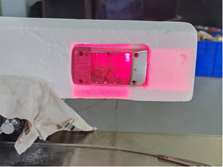
Field tests demonstrated the formation of rectangular light spots and their coverage on various material surfaces. Light intensity uniformity and temperature uniformity must be quantitatively evaluated, while field photos are used primarily to record spot shape, boundaries, and coverage status.
1. Project Objectives
- Generate surface heat source: Redistribute Gaussian peak energy over a 2D area to create a rectangular or square beam spot that matches the specimen's geometry.
- Control Center Hotspot: Minimize energy disparity between center and edge to reduce risks of local ablation, coating damage, thermal stress concentration, and temperature overshoot.
- Maintain clear boundaries: cover the effective test area to prevent non-target irradiation of fixtures, temperature measurement lines, and surrounding structures.
- Achieve repeatable alignment: Maintain consistent spot position and incident angle by fixing working distance, reference plane, optical axis adjustment, and locking mechanism.
II. Principles of Beam Shaping from Gaussian to Flat-Top
The transverse intensity of an ideal Gaussian beam is given by I(r) = I₀·exp(-2r²/w²), with peak intensity at the center that gradually decreases toward the edges. The goal of a flat-top beam is to maintain power density as constant as possible within the effective aperture and drop rapidly at the edges.
This case employs a static beam shaping approach: first stabilize the input beam's diameter and divergence angle, then use shaping optics to redistribute energy, and finally form the target rectangular spot on the work surface with imaging optics. This process relies on energy redistribution rather than simple truncation.
III. System Stages and Control Points
| step | Primary Function | Parameters to control |
|---|---|---|
| Laser light source | Provide continuous or modulated optical power | Wavelength, power, beam quality, power stability |
| Beam expansion and collimation | Match shaper input aperture and reduce divergence | beam waist, divergence angle, coaxiality, lens damage threshold |
| Beam shaping | Map Gaussian distribution to an approximate flat-top distribution | Input specifications, uniformity, efficiency, edge steepness |
| Image Projection | Generate target light spots with specified dimensions and shapes | Working distance, magnification, defocus amount, incident angle |
| Temperature Control | Adjust laser power using temperature feedback | Emissivity, Sampling Interval, PID Parameters, Over-Temp Interlock |
Common beam shaping approaches include refractive shapers, microlens arrays or integrators, diffractive optical elements, and scan overlap. Each method has different requirements for beam quality, wavelength, working distance, efficiency, and defocus; select the approach based on your project's light source and target thermal field.
IV. Solution Design Input
Engineering design should first define the light source, target area, and sample conditions to determine the shaping and projection strategy.
| No. | Add Project | Content to be clarified |
|---|---|---|
| 1 | Lighting conditions | Laser wavelength, output power, and power stability |
| 2 | Input Beam | Beam diameter, beam quality M², and divergence angle |
| 3 | Target Spot | Rectangular or square spot size, coverage area, and boundary requirements |
| 4 | Installation Requirements | Working distance, incident angle, optical axis position, and alignment reference |
| 5 | Sample Condition | Material, Thickness, Surface Condition, and Absorption Characteristics |
| 6 | Thermal Test Requirements | Target temperature curve, heating process, and uniformity requirements |
| 7 | Telemetry and Boundaries | Temperature measurement method, fixture heat dissipation, thermal insulation, and safety interlock requirements |
5. Absorbed Heat Flux and Temperature Distribution
The heat flux absorbed by the sample surface can be approximated as the product of incident intensity and absorptivity: q″abs(x,y) = α(λ, T, Surface Condition)·I(x,y). Absorptivity depends on laser wavelength, temperature, and surface condition.
Even with near-uniform incident light intensity, variations in material absorption, fixture contact, and edge heat dissipation can still cause temperature gradients. Therefore, a control strategy combining optical homogenization, thermal boundary optimization, and closed-loop temperature correction is recommended.
VI. Engineering Control Strategies
- Select a rectangular spot size and power margin based on the sample dimensions to avoid losing significant energy with apertures.
- Evaluate metal reflectivity, incident angle, and backscatter risk; apply absorptive coatings or light traps as needed.
- Control edge heat dissipation and temperature rise in non-target areas using thermal insulation, water-cooled fixtures, or low-thermal-conductivity supports.
- Adjust power using thermocouples, infrared sensing, or thermal imaging feedback; set heating ramp rate and over-temperature limit.
- Under complex boundary conditions, further employ zone modulation, scan trajectory, or model predictive control.
7. On-Site Testing and Observation
Spot patterns and coverage were evaluated on metal samples, a white calibration screen, refractory material with a rough surface, and white insulating material. Metal samples were clamped and protected from non-target areas using insulating material. The calibration screen was used to verify spot contour, size, rectangular boundaries, and macroscopic brightness distribution. Quantitative uniformity assessment shall be performed using a beam profiler or a calibrated camera system.
Refractory material test plates assess light spot retention under varying surface morphologies and absorption characteristics. Reflection and scattering on white insulating materials affect camera-recorded brightness; thus, incident heat flux cannot be inferred directly from visual or photographic luminance. On-site images support evaluation of rectangular spot formation and surface coverage capability. However, thermal field metrics require validation through quantitative optical calibration and actual specimen temperature measurements.
8. Performance Evaluation and Acceptance Recommendations
Measure field uniformity at the actual working distance and target plane. Within the specified region of interest (ROI), calculate average power density, maximum, minimum, peak-to-valley difference, or coefficient of variation. Record spot size, edge characteristics, and long-term drift. When using a camera, avoid saturation and apply linear, dark-field, and pixel response corrections.
Temperature distribution is determined by the incident light field, material absorptivity, thickness, thermal conductivity, surface radiation, fixture heat dissipation, and boundary conditions. Validation should be performed on actual samples using thermal imaging, multi-point thermocouples, or two-color pyrometry. For highly reflective metals, evaluate emissivity errors by measuring from the backside, applying calibration coatings, or cross-validating with both contact and non-contact methods. While optical intensity uniformity correlates with temperature uniformity, they are not interchangeable.
| Acceptance Project | Recommended Method | Report Content |
|---|---|---|
| Spot size and shape | Calibration screen or beam analyzer | Width, Height, Edge Position, Working Distance |
| Light Intensity Uniformity | Attenuated beam analysis or scan power measurement | ROI, Average Value, Peak-to-Valley Difference, Uniformity Metric |
| Power Stability | Power meter continuous recording | Warm-up time, short-term fluctuation, long-term drift |
| Temperature Uniformity | Thermal imaging or multi-point thermocouple measurement | Sensor placement, emissivity, steady-state temperature difference, heating curve |
| Repetition | Multiple Fixtures and Cyclic Testing | Spot position, temperature curve, and peak deviation |
9. Use Cases
- Material Thermal Response: Localized Surface Heating, Thermal Cycling, and Thermal Shock of Coatings, Metals, Ceramics, and Composites
- Structural Thermal Load: Apply a controllable surface heat flux to a specified rectangular region under constraints imposed by the fixture and non-target areas.
- Thermo-mechanical Coupling Test: Integrates with tensile, compression, fatigue, or vibration platforms to synchronize temperature and mechanical loading.
- Vacuum and Atmosphere Environments: Enables non-contact heating through a window, reducing in-chamber heat sources, wiring, and structural footprint.
10. Safety and Engineering Precautions
High-power laser surface heating involves direct beams, specular reflection, diffuse reflection, hot surfaces, smoke, and fire hazards. The system must incorporate a closed optical path, key switch, door interlock, shutter, emergency stop, and over-temperature interlock. High-power beam traps should be installed around reflective workpieces. Visible red or pink light in site photos cannot determine the wavelength or safety class of the invisible primary laser; actual protection measures must be based on the equipment's wavelength, power, and risk assessment.
11. Project Summary
This case demonstrates beam shaping to redistribute the peak energy of a Gaussian beam, forming a rectangular flat-top spot on the target plane. On-site testing validated the spot's formation and coverage across different material surfaces, providing engineering reference for localized surface heating and thermal load experiments.
Engineering applications must account for optical uniformity, material absorption, and thermal boundary conditions. Final thermal field performance should be evaluated through actual light field calibration and sample temperature measurements. Equipment parameters shall be based on the project's light source, beam shaper specifications, and calibration records.
Need something similar?
Our technical team delivers customized laser heating solutions tailored to your specific needs.
Contact Us